
A light-duty steel-concrete prefabricated floor pouring molding machine with shaped lightweight filler

A molding machine and filling material technology, which is applied in ceramic molding machines, ceramic molding workshops, manufacturing tools, etc., can solve the problem of one-time simultaneous pouring of prefabricated bottom plates that cannot meet the production requirements of prefabricated bottom plates of laminated floor slabs and cannot realize new laminated floor slabs. Forming and other problems to achieve the effect of improving efficiency

Inactive Publication Date: 2016-02-10
HUBEI HONGYI BUILDING DECORATION ENG
View PDF5 Cites 1 Cited by
  • Summary
  • Abstract
  • Description
  • Claims
  • Application Information

AI Technical Summary

Problems solved by technology

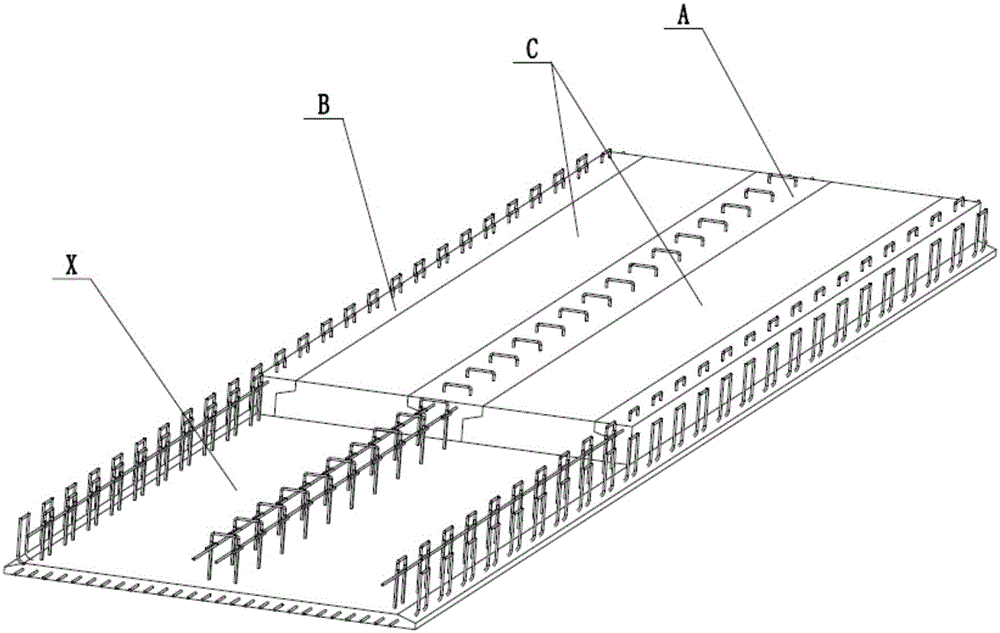
[0002] Laminated slabs are widely used in modern buildings. The so-called laminated slabs are composed of upper slabs and lower slabs. The lower slabs are prefabricated slabs, and the upper slabs are cast-in-place slabs poured on site. The basic form of the lower slabs of the laminated slabs is A single reinforced concrete prefabricated slab, but with the development of the construction industry, new requirements have been put forward for the energy saving, environmental protection and light weight of the laminated floor slab. The single reinforced concrete prefabricated lower slab can no longer meet the growing needs. Concrete bottom layer and different forms of steel-concrete prefabricated floor with shaped lightweight fillers are applied, and the existing machinery is limited to pouring a single concrete material on the formwork with pre-bound steel bars to form a steel-concrete prefabricated floor, which cannot meet the changes. The production requirements of various laminated floor prefabricated floor slabs, and the one-time synchronous pouring and forming of the prefabricated floor of the new laminated floor slab containing lightweight filling materials cannot be realized

Method used


Image

  • A light-duty steel-concrete prefabricated floor pouring molding machine with shaped lightweight filler
  • A light-duty steel-concrete prefabricated floor pouring molding machine with shaped lightweight filler
  • A light-duty steel-concrete prefabricated floor pouring molding machine with shaped lightweight filler

Examples


Embodiment Construction

[0018] How to implement the present invention will now be further explained in conjunction with the drawings:

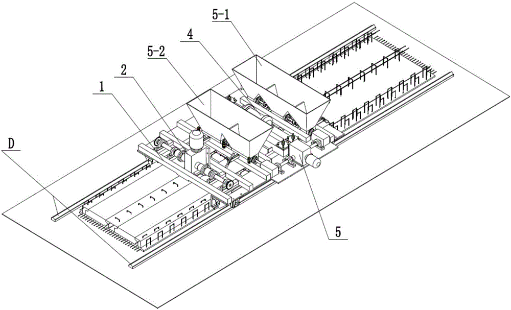
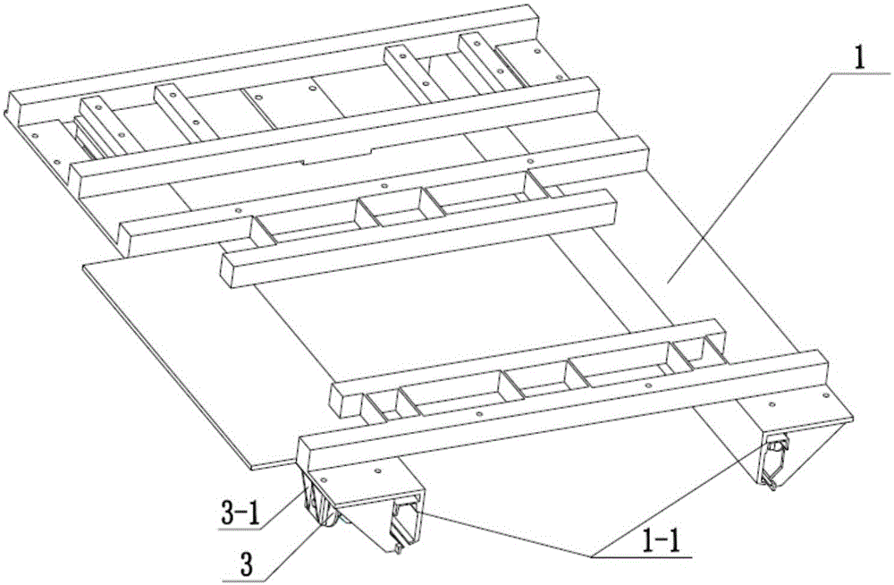
[0019] The present invention is a light-weight steel-concrete prefabricated bottom plate pouring molding machine with molded light-weight fillers, see figure 2 , Including frame 1, driving wheel system 2, guide wheel system 3, vibration forming system 4 and material system 5. The frame 1 is composed of longitudinal two sides of the template 1-1 and horizontal fixed beams, the guide wheel system 3 Two sets of guide wheel sets are respectively arranged on both sides of the front end of the frame 1 through the guide wheel support 3-1, see image 3 , The two drive wheel sets 2-1 of the drive wheel system 2 are respectively fixed on both sides of the rear end of the frame 1 through the drive wheel supports 2-1a; the drive wheel sets are driven by the motor to run synchronously, and the frame follows the ground track D operation; vibration forming mechanism 4 is composed of v...


PUM


Abstract

The invention relates to a pouring molding machine for a light steel mixed prefabricated base plate with molding light fillers, and belongs to the field of building material machinery equipment. A steel mixed light molding plate middle steel mixed main rib molding area, a steel mixed longitudinal edge molding area and a light filler molding area correspondingly formed between the steel mixed light molding plate middle steel mixed main rib molding area and the steel mixed longitudinal edge molding area are respectively formed by concrete vibration molding separation plates of a vibration molding mechanism of the pouring molding machine. A discharging port of a concrete material hopper and a discharging port of a light filler material hopper of a material system correspond to the steel mixed main rib molding area, the steel mixed longitudinal edge molding area and the light filler molding area respectively, the discharging ports are controlled by a flow controller and respectively feed the concrete materials and the light filler materials into the corresponding steel mixed longitudinal edge molding area, the corresponding steel mixed main rib molding area and the corresponding light filler molding area, the light steel mixed prefabricated base plate with the molding light fillers is accordingly molded through vibration of the vibration molding mechanism, one-time simultaneous feeding molding on the two different materials is completed, and mechanical high-efficiency production on the light composite floor prefabricated base plate is achieved.

Description

Technical field [0001] The invention provides a light-weight steel-concrete prefabricated bottom plate pouring and molding machine with molded light-weight fillers, which belongs to the field of building materials machinery and equipment. Background technique [0002] Laminated floor slabs are widely used in modern buildings. The so-called laminated floor slab is composed of an upper slab and a lower slab. The lower slab is a prefabricated slab, and the upper slab is a cast-in-situ slab cast on site. The basic form of the lower slab is A single reinforced concrete precast slab, but with the development of the construction industry, new requirements have been put forward for the energy saving, environmental protection and light weight of the laminated floor. A single reinforced concrete precast lower slab can no longer meet the increasing demand. The concrete bottom layer is applied with different forms of steel-concrete prefabricated slabs containing shaped lightweight fillers. H...

Claims


Application Information

Patent Timeline
Patent Type & Authority Patents(China)
IPC IPC(8): B28B15/00B28B1/08B28B13/02
CPCB28B1/087B28B13/02B28B15/00
Inventor 吴顺红王少重黄胜夏继张军
Owner HUBEI HONGYI BUILDING DECORATION ENG
Learn More