Ultra-high-pressure axial plunger pump

A technology of axial piston pump and ultra-high pressure, which is applied in the direction of pumps, liquid variable displacement machines, machines/engines, etc., and can solve difficult problems

Inactive Publication Date: 2014-04-09
GUANGDONG HUAYE POWER TECH
View PDF6 Cites 0 Cited by
  • Summary
  • Abstract
  • Description
  • Claims
  • Application Information

AI Technical Summary

Problems solved by technology

It is very difficult for ordinary plunger pumps to achieve ultra-high pressures above 100Mpa, and it is even more difficult to achieve ultra-high pressures above 120Mpa.

Method used


Image

  • Ultra-high-pressure axial plunger pump
  • Ultra-high-pressure axial plunger pump
  • Ultra-high-pressure axial plunger pump

Examples


Embodiment 1

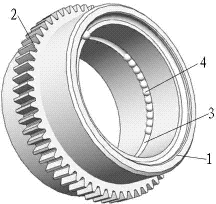
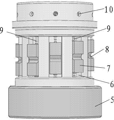
[0033] Example 1, such as figure 1 with figure 2 As shown, the ultra-high pressure axial piston pump of the present invention includes a cylindrical pump body 5; several strip-shaped sliding holes 6 are evenly distributed on the circumferential wall of the pump body 5, wherein each sliding hole 6 is arranged There is a slide block 7 that can slide relatively, and the two ends of the slide block 7 are respectively connected with a small plunger pump 9, and the small plunger pump 9 is placed in the wall at both ends of the sliding hole 6 on the pump body 5, so that Both ends of the pump body 5 are provided with an oil inlet and an oil outlet corresponding to the small plunger pump 9; a spinning drive mechanism driven by a motor 21 is provided inside or outside the pump body 5, The spinning driving mechanism cooperates with the slider 7 in the pump body 5 or outside the pump body 5, so that the rotation of the spinning driving mechanism can drive the slider 7 to slide axially i...

Embodiment 2

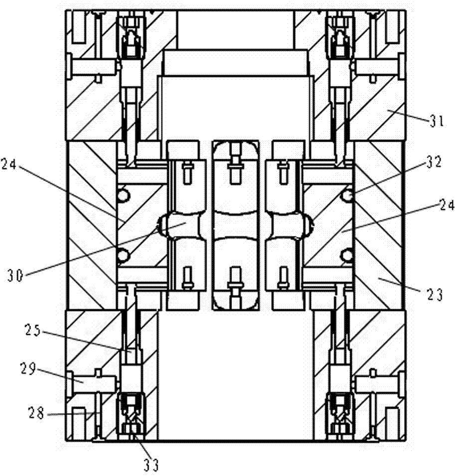
[0035] Example 2 as image 3 with Figure 4 As shown, the ultra-high pressure axial piston pump of the present invention includes a cylindrical pump body 26; a number of elongated sliding holes 6 are evenly distributed on the circumferential wall of the pump body 26, wherein each sliding hole 6 is arranged There is a slide block 24 that can slide relatively, and the two ends of the slide block 24 are respectively connected with a small plunger pump 25, and the small plunger pump 25 is placed in the wall at both ends of the sliding hole 6 on the pump body 26, so that Both ends of the pump body 26 are provided with an oil inlet and an oil outlet corresponding to the small plunger pump 25; a spinning drive mechanism driven by a motor 21 is provided inside or outside the pump body 26, The spinning drive mechanism cooperates with the slider 24 in the pump body 26 or outside the pump body 26, so that the rotation of the spinning drive mechanism can drive the slider 24 to slide axia...


PUM


Abstract

The invention discloses an ultra-high-pressure axial plunger pump, which belongs to the field of ultra-high-pressure technologies. According to the ultra-high-pressure axial plunger pump disclosed by the invention, a plurality of strip-shaped slide holes are uniformly distributed in the circumferential wall of a pump body, wherein a slide block capable of relatively sliding is arranged in each of the slide holes, small plunger pumps are connected to the both ends of the slide block respectively, the small plunger pumps are arranged in walls at the both ends of each of the slide holes in the pump body, and an oil inlet and an oil outlet corresponding to the each of the slide holes are formed in the both ends of the pump body; a spinning drive mechanism driven by a motor is arranged in the pump body or outside the pump body, the spinning drive mechanism is cooperated with the slide blocks in the pump body or outside the pump body, thus the slide blocks can be driven by the rotation of the spinning drive mechanism to axially slide in the slide holes, and drive plungers in the small plunger pumps to move back and forth. The ultra-high-pressure axial plunger pump disclosed by the invention is capable of realizing a variable pressure and a variable flow; moreover, a plurality of pumps can be connected in parallel, thus meeting oil supply for a large hydraulic station; an ultra-high-pressure working pressure of more than 120 MPa can be generated.

Description

technical field [0001] The invention relates to the field of ultra-high pressure technology, in particular to an ultra-high pressure axial piston pump. Background technique [0002] As the market heats up, plunger pump manufacturers continue to emerge, and there are more and more plunger pump products from different manufacturers and models. The plunger pumps commonly used at home and abroad are all pumps that reciprocate in the pump cylinder through a single plunger, so that the volume between the plunger and the pump wall changes, and the pump repeatedly sucks and discharges liquid and increases its pressure. It is very difficult for ordinary plunger pumps to achieve ultra-high pressures above 100Mpa, and it is even more difficult to achieve ultra-high pressures above 120Mpa. Contents of the invention [0003] The purpose of the present invention is to provide an ultra-high pressure axial piston pump for the above problems, which can realize variable pressure and variab...

Claims


Application Information

Patent Timeline
Patent Type & Authority Applications(China)
IPC IPC(8): F04B17/03
Inventor 吴锡树吕百英
Owner GUANGDONG HUAYE POWER TECH
Why Eureka
Try Eureka