
Method for measuring phase to phase mutual impedance of long-distance extra-high voltage common-tower double-circuit transmission line

A technology of mutual impedance between phases and dual circuits on the same tower. It is applied in the field of power transmission and transformation testing and can solve problems such as interference.

Active Publication Date: 2014-04-09
STATE GRID CORP OF CHINA +1
View PDF6 Cites 16 Cited by
  • Summary
  • Abstract
  • Description
  • Claims
  • Application Information

AI Technical Summary

Problems solved by technology

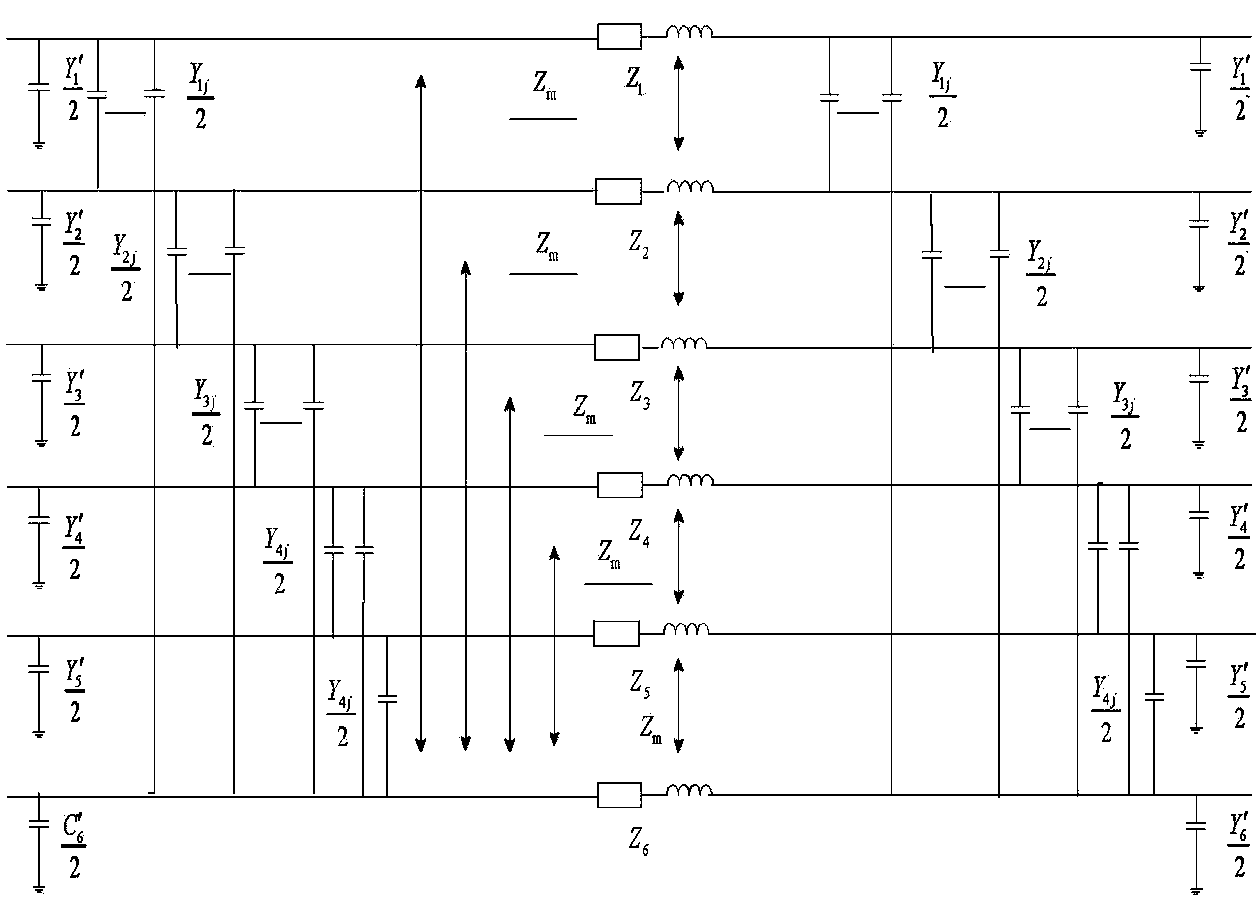
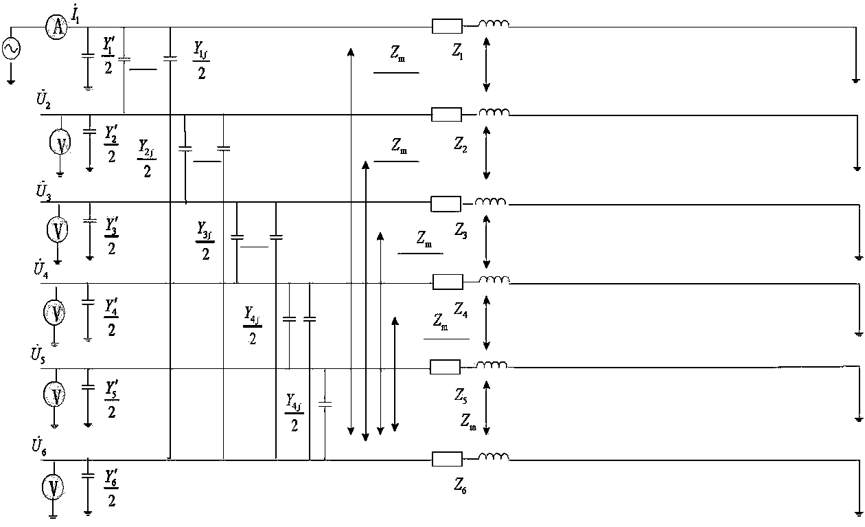
[0003] The purpose of the present invention is to propose a technical scheme for measuring mutual impedance between phases of long-distance ultra-high voltage double-circuit transmission lines on the same tower. In the scheme, different frequency power supply is used to solve the problem of power frequency interference, and the mutual impedance between phases of long-distance lines is used to correct The algorithm overcomes the influence of phase-to-phase capacitance and ground capacitance on the mutual impedance between phases, and this method is applicable to the measurement of mutual impedance between lines with different lengths

Method used


Image

  • Method for measuring phase to phase mutual impedance of long-distance extra-high voltage common-tower double-circuit transmission line
  • Method for measuring phase to phase mutual impedance of long-distance extra-high voltage common-tower double-circuit transmission line
  • Method for measuring phase to phase mutual impedance of long-distance extra-high voltage common-tower double-circuit transmission line

Examples


Embodiment Construction

[0041] A method for measuring mutual impedance between phases of long-distance ultra-high voltage double-circuit transmission lines on the same tower, which is the measurement of mutual impedance between phases of six-phase transmission lines A1, B1, C1, A2, B2, and C2 with a frequency of 50 Hz and more than 240 kilometers on the same tower. A measurement method, wherein the method comprises:

[0042] Step 1: Obtain the phase-to-phase mutual impedance values ​​at two frequencies whose upper and lower absolute error values ​​are equal with the 50Hz frequency as the midpoint;

[0043] Step 2: average the two inter-phase mutual impedance values ​​to obtain an average value of the inter-phase mutual impedance at two frequencies, and the average value is the inter-phase mutual impedance value at a frequency of 50 Hz.

[0044] In an embodiment, the absolute error value is 1.5Hz to 3Hz.

[0045] In the embodiment: the 50Hz frequency is the phase-to-phase mutual impedance value under...


PUM


Abstract

The invention discloses a method for measuring phase to phase mutual impedance of a long-distance extra-high voltage common-tower double-circuit transmission line. The method comprises the first step that the head end of a measured phase is in an open circuit, the tail end of the measured phase is in ground connection, the head ends of other phases are in an open circuit, the tail ends of other phases are in ground connection, voltages are applied to the head end of the measured phase, currents are injected into the head end of the measured phase, and the current signal of the head end of the measured phase and the induction voltage signals of the head ends of other phases under two frequencies are synchronously measured; the second step that the voltage signals and the current signals under the two frequencies are obtained through an FFT filtering algorithm; the third step that phase to phase mutual impedance values under the two frequencies are respectively calculated according to the voltage signals and the current signals under the two frequencies, and a phase to phase mutual impedance value under the frequency of 50Hz is obtained by averaging the two phase to phase mutual impedance values. According to the method, a traditional measurement method is changed, the influence of line distribution parameter characteristics and induction voltage phases and the existence of power frequency interference are considered in the line connection mode and the algorithm, and especially in the long-distance transmission line, the errors of the phase to phase mutual impedance value measured through the method are reduced, and engineering needs are met.

Description

technical field [0001] The invention belongs to power transmission and transformation testing, and in particular relates to a method for measuring the mutual impedance between phases of a long-distance ultra-high voltage double-circuit transmission line on the same tower. Background technique [0002] For the measurement of mutual impedance between phases of long-distance double-circuit transmission lines on the same tower, traditional measurement methods often produce large errors due to the mutual influence of line phase conductor capacitance and impedance and the existence of power frequency interference. The longer the line distance, the greater the error , such errors may not be tolerated in engineering applications. Contents of the invention [0003] The purpose of the present invention is to propose a technical scheme for measuring mutual impedance between phases of long-distance ultra-high voltage double-circuit transmission lines on the same tower. In the scheme, ...

Claims


Application Information

Patent Timeline
IPC IPC(8): G01R27/16G01R27/08
Inventor 傅中夏令志叶剑涛王贻平程登峰王庆军刘静杨道文章炜赵常威
Owner STATE GRID CORP OF CHINA
Learn More