Partial discharge monitoring system and method based on m-bus

A partial discharge monitoring, M-BUS technology, applied in the direction of testing dielectric strength, etc., can solve the problems of high equipment cost, certain requirements for the sampling rate of the acquisition system, requirements for the sampling rate of the acquisition system, etc., achieve high sensitivity, improve equipment The effect of safe operation and improving the level of intelligence

Active Publication Date: 2019-04-05
胡岳
View PDF6 Cites 0 Cited by
  • Summary
  • Abstract
  • Description
  • Claims
  • Application Information

AI Technical Summary

Problems solved by technology

[0009] The disadvantage of the first solution is that because the sensor is set far away from the equipment, because of the attenuation of the signal in the air, this technology is suitable for relatively obvious partial discharge detection, and the equipment cost is relatively high
This system can realize synchronous monitoring of multiple electrical equipment in one system, but the disadvantage of the system is that it has certain requirements on the sampling rate of the acquisition system, and the accuracy of signal time difference calculation also poses a challenge to the connection distance of adjacent sensors on the signal bus. certain requirements
[0011] The disadvantage of the second solution is that there are certain requirements for the sampling rate of the acquisition system

Method used


Image

  • Partial discharge monitoring system and method based on m-bus
  • Partial discharge monitoring system and method based on m-bus
  • Partial discharge monitoring system and method based on m-bus

Examples


Embodiment Construction

[0064] The present invention will be described in detail below in conjunction with specific embodiments. The following examples will help those skilled in the art to further understand the present invention, but do not limit the present invention in any form. It should be noted that those skilled in the art can make several modifications and improvements without departing from the concept of the present invention. These all belong to the protection scope of the present invention.

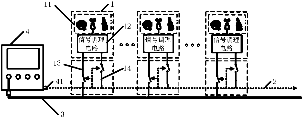
[0065] The basic principles of the technical solution of the present invention are as figure 1 Shown: Multiple PD sensing circuits S i (i=1~n) The sensed signal is connected to the same high-frequency shielded signal bus through a three-way connector (N-type three-way joint). The partial discharge signal detected by the partial discharge sensor in each partial discharge sensing circuit is amplified by an amplifier, pre-filtered and detected, and the frequency is reduced to form a detection pulse ...


PUM


Abstract

The invention provides a partial discharge monitoring system and method based on M-BUS. The system comprises multiple partial discharge sending circuits, a high-frequency shielding signal bus, a M-BUS control line and a data acquisition and control terminal. The multiple partial discharge sending circuits are connected in parallel to a same high-frequency shielding signal bus for uploading the detected partial discharge signals to the high-frequency shielding signal bus. The high-frequency shielding signal bus is used to connect the multiple partial discharge sending circuits, wherein one end of the high-frequency shielding signal bus is connected with the data acquisition and control terminal, and the other end of the high-frequency shielding signal bus is an open-circuit end. The M-BUS control line is used to control a signal switching circuit and a power switching circuit. The data acquisition and control terminal is connected with the high-frequency shielding signal bus and the M-BUS control line separately. The method of the invention is a partial discharge monitoring method having advantages of simple installation and commissioning and high sensitivity and accuracy, can be used to perform on-line monitoring on multiple electrical equipment in the whole substation to timely find out the insulation defect and achieve initial positioning, so the equipment operation safety can be improved.

Description

technical field [0001] The invention relates to a signal monitoring and positioning method, in particular to an online monitoring and positioning method of multi-source partial discharge signals in a substation, and in particular to a partial discharge monitoring method and system based on M-BUS. Background technique [0002] As an important means of insulation diagnosis, partial discharge detection is being popularized by the power sector because it can reflect the insulation status of electrical equipment in the power system in a timely and effective manner. [0003] At present, researches on partial discharge monitoring and monitoring technology are basically carried out for specific power equipment in substations at home and abroad. The main detection principles and methods used include pulse current method, ultra-high frequency method (UHF), ultrasonic method, chemical method, and optical method. Among them, the UHF method and the ultrasonic method are more practical an...

Claims


Application Information

Patent Timeline
Patent Type & Authority Patents(China)
IPC IPC(8): G01R31/12
Inventor 胡岳
Owner 胡岳
Why Eureka
Try Eureka