
Modular electronic-controlled engine model

An electronically controlled engine and engine technology, applied in the field of teaching aids, can solve the problems of complex parts, bulky, inconvenient disassembly, and assembly, and achieve the effects of easy understanding, improved interchangeability, and easy assembly

Active Publication Date: 2014-04-09
GUANGXI UNIV
View PDF9 Cites 12 Cited by
  • Summary
  • Abstract
  • Description
  • Claims
  • Application Information

AI Technical Summary

Problems solved by technology

[0003] The purpose of the present invention is to provide a modular electronically controlled engine model to solve the problems in the engine teaching practice that the traditional engine model has complex and heavy parts, inconvenient disassembly and assembly; the working process of the engine is not intuitive enough, and the function of the engine model is single Through the modular electronic control engine model, students can strengthen their understanding of the working process of engines with different forms and cylinder numbers, smooth ignition and valve opening and closing timing, and also exercise students' hands-on ability and programming ability

Method used


Image

  • Modular electronic-controlled engine model
  • Modular electronic-controlled engine model
  • Modular electronic-controlled engine model

Examples


Embodiment Construction

[0017] The technical solutions of the present invention will be further described below through the accompanying drawings and embodiments.

[0018] The modular electronically controlled engine model of the present invention is further described by taking the technical solutions of a 6-cylinder in-line engine model, an 8-cylinder V-shaped engine model, and a 4-cylinder opposed engine model as examples.

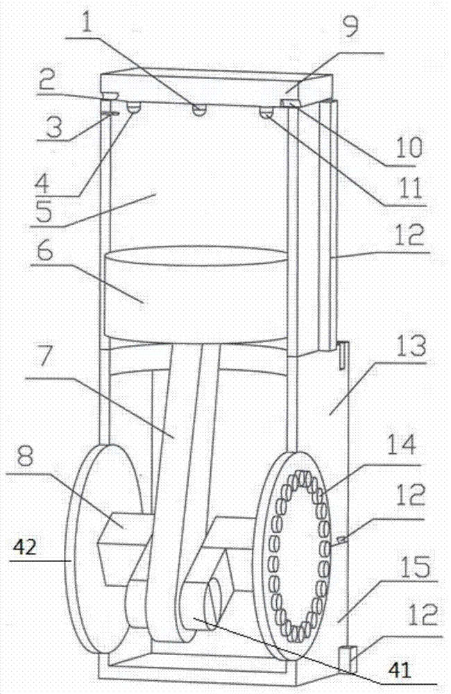
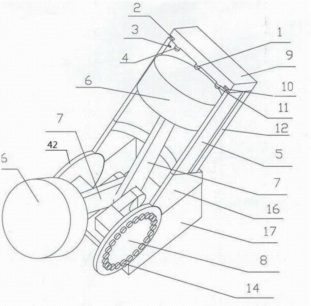
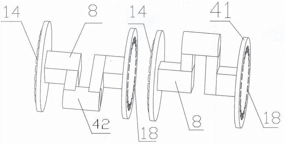
[0019] Such as figure 1 As shown, the in-line and opposed single-cylinder engine model structures of the present invention are composed of ignition LED lamp 1, intake valve 2, position sensor 3, intake LED lamp 4, cylinder 5, piston 6, connecting rod 7. Crank throw 8, cylinder head 9, exhaust valve 10, exhaust LED lamp 11, dovetail groove structure 12, crankcase upper case 13, crank throw 8 connecting boss 14 and crankcase lower case 15. The cylinder head 9 is fixed on the cylinder 5 through the dovetail groove structure 12, the ignition LED light 1 is located in the middle of...


PUM


Abstract

The invention discloses a modular electronic-controlled engine model. The modular electronic-controlled engine model comprises a mechanical portion and a control circuit portion. In the mechanical portion, a piston, a connecting rod, a crank, a cylinder, a cylinder cover and a crankcase are assembled into a single-cylinder engine model, and then multiple single-cylinder engine models are assembled into a in-line type V-shaped opposite-type multicylinder engine model. The control portion is composed of a single chip microcomputer, a position sensor, LED lamps and a power source. The position sensor is located at the upper dead center of the cylinder, and used as the input single of the single chip microcomputer to control the operation of the LED lamps. The lighting of the yellow LED lamp indicates the ignition working condition. The lighting of the red LED lamp indicates the inlet valve opening condition. The lighting of the greed LED lamp indicates the exhaust valve opening condition. By observing the LEDs and the movement of the piston, the multicylinder engine successful ignition time and the inlet valve and exhaust valve opening and closing time can be obtained. The modular electronic-controlled engine model of the invention can be used in the engine teaching practices in universities to help students to understand the working sequence and valve opening and closing time of different types of engines having different cylinder number.

Description

technical field [0001] The invention relates to a teaching tool, in particular to a modular electric control engine model. Background technique [0002] At present, in the practice of engine teaching in colleges and universities, due to the complex and bulky parts of traditional engine models, it is inconvenient to disassemble and assemble. Moreover, the engine models are all in fixed form and have a single function. The working process of the engine is not intuitive enough, and the teaching effect is not very ideal, which is not conducive to students' understanding of the working process of the engine. Contents of the invention [0003] The purpose of the present invention is to provide a modular electronically controlled engine model to solve the problems in the engine teaching practice that the traditional engine model has complex and heavy parts, inconvenient disassembly and assembly; the working process of the engine is not intuitive enough, and the function of the e...

Claims


Application Information

Patent Timeline
IPC IPC(8): G09B25/02
Inventor 刘晓红雷发荣梁圣秋丁宏飞阎凌云张琛
Owner GUANGXI UNIV
Learn More