A multi-antenna array supporting multi-standard

A multi-antenna, multi-mode technology, applied in the field of communication, can solve the problems of high installation error rate, signal inter-frequency interference, and increase the cost of radiation units, etc., to reduce inter-frequency interference, reduce design costs, and reduce the probability of installation errors Effect

Active Publication Date: 2016-09-14
WUHAN HONGXIN TELECOMM TECH CO LTD
View PDF2 Cites 0 Cited by
  • Summary
  • Abstract
  • Description
  • Claims
  • Application Information

AI Technical Summary

Problems solved by technology

[0005] For the method (1), the problem is that when using a base station antenna that supports multiple frequency bands in engineering, the common practice is to add a combiner at the signal input or output port of the base station antenna to realize the signal separation of different systems
However, this method is prone to severe signal cross-frequency interference and high installation error rate. The main limitation is that it cannot independently control signals that support different standards.
[0006] For (2), the problem is that when designing a base station antenna that supports multiple frequency bands, due to the existence of multiple radiating units and multiple sets of feeding networks, in order to avoid mutual interference between radiating units of different frequency bands, it is necessary to It is necessary to independently design the radiating unit and feed network working in different frequency bands
The main problem is that, for base station antennas, adding a set of radiation units will increase the cost of designing, processing, and installing the radiation units. Correspondingly, the design, processing, and installation of the radiation units will also increase the corresponding feed network cost

Method used


Image

  • A multi-antenna array supporting multi-standard
  • A multi-antenna array supporting multi-standard
  • A multi-antenna array supporting multi-standard

Examples


Embodiment Construction

[0103] In order to make the technical problems, technical solutions and beneficial effects to be solved by the invention clearer, the present invention will be further described in detail below in conjunction with the accompanying drawings and embodiments. It should be understood that the specific embodiments described are only used to explain the present invention, not to limit the present invention.

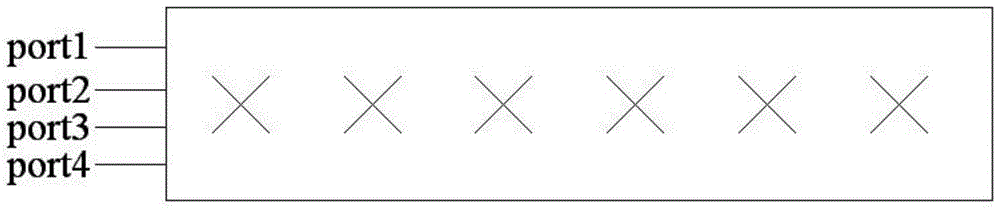
[0104] Such as figure 1 , is a schematic diagram of the overall structure of the present invention.

[0105] Specifically, a multi-mode multi-antenna array is composed of a radiation unit 311, a reflector 313, a feed network arranged on the back of the reflector, and a set of antenna input and output ports port1, port2, port3, and port4. .

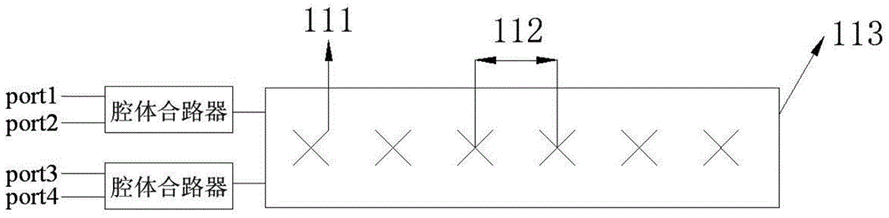
[0106] Such as figure 2 , is method (1): a schematic diagram of a radiation unit realizing multi-band operation in the prior art.

[0107] The radiating unit of this method is a broadband or ultra-broadband radiating unit, which is ins...


PUM


Abstract

A multi-mode-supported multi-antenna array is provided in the present invention, comprising more than two radiating units with the same form, a reflecting plate, a feed network and a set of input / output ports. The radiating units and the feed network are respectively positioned on the two different sides of the reflecting plate. The radiating units implement electrical connection with each other via the feed network. The input / output ports of the antenna connect with the feed network, and radio frequency signals are received or transmitted by the set of input / output ports. With the present invention, high-frequency signal input / output ports and low-frequency signal input / output ports can be independently controlled, so that ±45 degree bipolar signal coverage can be respectively performed. The array is simple in structure and low in cost.

Description

technical field [0001] The invention belongs to the technical field of communication, and in particular relates to a multi-system multi-antenna array, and the invention can be widely used in the field of mobile communication base station antennas. Background technique [0002] The development of the mobile communication industry has gone through the process from 2G to 3G, and from 3G to 4G. The needs of users have gradually shifted from voice calls to data services, and from data services to high-speed data services. In this process, 2G, 3G and 4G will coexist for a long time. For mobile communication base station antennas, the existence of a multi-standard system requires the antenna to support multi-band work. At present, there are two main design methods for base station antennas that support multi-band operation: [0003] (1) Design a broadband or ultra-wideband radiating unit and a feed network to support multi-band work at the same time; [0004] (2) Design a variet...

Claims


Application Information

Patent Timeline
Patent Type & Authority Patents(China)
IPC IPC(8): H01Q21/30H01Q23/00
CPCH01Q21/30H01Q21/08H01Q21/26H01Q25/04
Inventor 郭继权石萌李孜程猛王杰
Owner WUHAN HONGXIN TELECOMM TECH CO LTD
Why Eureka
Try Eureka