
busbar clamp

A technology of busbars and sub-busbars, applied in the field of busbar clamping, can solve the problems of reducing the carrying capacity of busbars, clamping busbars at the same time, and interference from surrounding personnel, so as to reduce vibration, improve versatility, and reduce vibration noise pollution effect

Active Publication Date: 2016-04-06
山西尚宽电气集团有限公司
View PDF9 Cites 0 Cited by
  • Summary
  • Abstract
  • Description
  • Claims
  • Application Information

AI Technical Summary

Problems solved by technology

[0002] At present, the support methods of busbar are generally two types: insulator support and ordinary busbar clamp support. , but because it is inevitable to drill holes in the busbar, the current carrying capacity of the busbar is reduced. In addition, when the busbar expands with heat and contracts with cold, the resulting length change cannot be compensated, and the stress will be fully applied to the insulator , in severe cases even lead to breakage of insulators;
[0003] When the common busbar clamp supports the busbar, generally, there will be a gap between the busbar clamp and the busbar in the width direction or thickness direction of the busbar, so that the busbar clamp cannot be clamped in the width direction and thickness direction of the busbar at the same time. Tighten the busbar; when the busbar passes through the AC current, because the electromotive force applied to the busbar is an alternating force with the same frequency as the current, there will be a situation where the busbar keeps beating the busbar clamps, and because the ordinary busbar The commonly used materials for busbar clamps are hard insulating materials, so it will generate large vibration noise, which will not only cause disturbance to surrounding personnel, but also affect the safe operation of equipment; in addition, common busbar clamps are very poor in versatility. Busbars with specifications and specific arrangement must be equipped with specific busbar clips. If the specification or arrangement of the busbars is changed, the busbar clips must be replaced, which brings a lot of inconvenience to the procurement and management of busbars

Method used


Image

  • busbar clamp
  • busbar clamp
  • busbar clamp

Examples


Embodiment 1

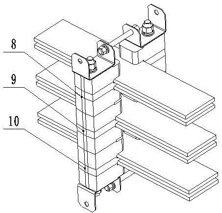
[0040] Such as Figure 3~5 Shown, present embodiment one by structure such as figure 2 The shown first unit busbar clamp 8, second unit busbar clamp 9 and third unit busbar clamp 10 are combined, the first unit busbar clamp 8, the second unit busbar clamp 9 and the third unit busbar clamp The clamps 10 are arranged next to each other from top to bottom. The above three unit busbar clamps share the same first stud 3, second stud 4 and corresponding nuts, and are located below the first unit busbar clamp 8. The gold fittings, the fittings above and below the busbar clamp 9 of the second unit, and the fittings above the busbar clamp of the third unit are removed, leaving only the fittings 8 above the busbar clamp of the first unit and the busbar of the third unit The hardware below the clamp 10 clamps each unit busbar clamp.

Embodiment 2

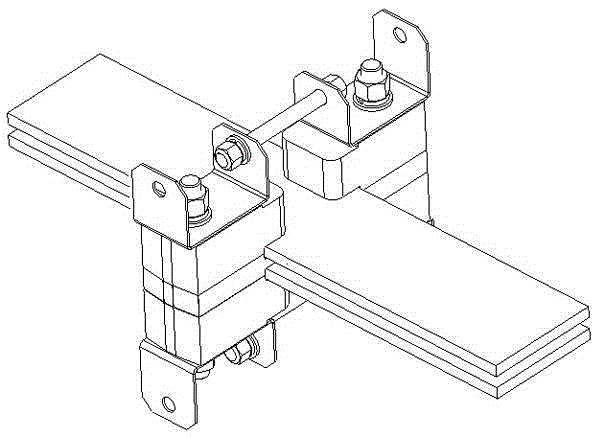
[0042] Such as Figure 6~9 As shown, the second embodiment consists of a structure such as figure 2 The fourth unit bus bar clamp 11, the fifth unit bus bar clamp 12 and the sixth unit bus bar clamp 13 are combined, the fourth unit bus bar clamp 11, the fifth unit bus bar clamp 12 and the sixth unit bus bar clamp The row clamps 13 are arranged next to each other in the horizontal direction, and the adjacent sub-mother-bar clamps 1 share a piece of hardware above and below them, and the fourth unit bus-bar clamp 11 and the fifth unit are connected by the shared hardware. The unit busbar clamp 12 and the sixth unit busbar clamp 13 are fixedly connected in sequence.

Embodiment 3

[0044] Such as Figure 10~13 Shown, present embodiment three by structure such as figure 2 The seventh unit busbar clamp 14, the eighth unit busbar clamp 15 and the ninth unit busbar clamp 16 are combined, and the arrangement of the seventh unit busbar clamp 14 and the eighth unit busbar clamp 15 is the same as the implementation In Example 1, the first unit busbar clip 8 and the second unit busbar clip 9 are arranged in a similar manner, while the arrangement of the eighth unit busbar clip 15 and the ninth unit busbar clip 16 is similar to that of the fourth unit in Example 2 The busbar clips 11 and the fifth unit busbar clips 12 are arranged in a similar manner.


PUM


Abstract

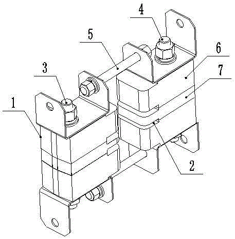
The invention discloses a busbar clamp, belongs to the technical field of busbar clamps, and aims to provide a busbar clamp which can clamp busbars in the width direction and the thickness direction of the busbars at the same time and is high in universality. According to the technical scheme, the busbar clamp comprises at least one unit busbar clamp; each unit busbar clamp comprises two sub busbar clamps, each sub busbar clamp comprises at least two insulating blocks, through holes are formed in all the insulating blocks, and the upper portion and the lower portion of each sub busbar clamp are respectively provided with a fitting; first studs thread all the insulating blocks and all the fittings together, and the insulating blocks and the fittings are clamped and fixed by nuts; first studs thread all the insulating blocks in the other sub busbar clamp and all the fittings together, and the insulating blocks and the fittings are clamped and fixed by nuts; every two adjacent fittings located on the same side of each sub busbar clamp are connected together through third studs and nuts, and the multiple unit busbar clamps are mutually parallel or perpendicular. The busbar clamp is suitable for the electric power department.

Description

technical field [0001] The busbar clip of the invention belongs to the technical field of busbar clips. Background technique [0002] At present, the support methods of busbar are generally two types: insulator support and ordinary busbar clamp support. , but because it is inevitable to drill holes in the busbar, the current carrying capacity of the busbar is reduced. In addition, when the busbar expands with heat and contracts with cold, the resulting length change cannot be compensated, and the stress will be fully applied to the insulator , in severe cases even lead to breakage of insulators; [0003] When the common busbar clamp supports the busbar, generally, there will be a gap between the busbar clamp and the busbar in the width direction or thickness direction of the busbar, so that the busbar clamp cannot be clamped in the width direction and thickness direction of the busbar at the same time. Tighten the busbar; when the busbar passes through the AC current, beca...

Claims


Application Information

Patent Timeline
Patent Type & Authority Patents(China)
IPC IPC(8): H02G5/00
Inventor 李强刘印德徐余杰申秀荣刘刚
Owner 山西尚宽电气集团有限公司
Learn More