Method for district cooling of internal cooling and external cooling of rotor magnetic pole
A technology of rotor magnetic poles and cold partitions, which is applied to the rotating parts of the magnetic circuit, the shape/style/structure of the magnetic circuit, etc., can solve the problems of unsatisfactory cooling effect, improve the cooling effect, improve the efficiency, and reduce the ventilation resistance. Effect
- Summary
- Abstract
- Description
- Claims
- Application Information
AI Technical Summary
Problems solved by technology
Method used
Image
Examples
Embodiment 1
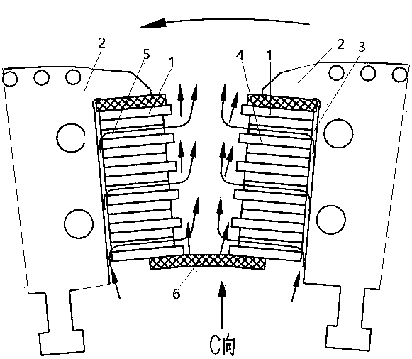
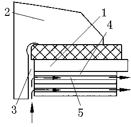
[0031] A method for sub-regional cooling between internal cooling and external cooling of rotor magnetic poles. The cooling gas flows into the channel between the two magnetic pole coils 1 through the ventilation partition device 6 on the air inlet end of the two magnetic pole coils 1 to form an external cooling ventilation air path, and The outside of the pole coil 1 is cooled, and at the same time the cooling gas flows into the inside of the pole coil 1 through the gap between the pole core 2 and the pole coil 1, forming an internal cooling ventilation air path, and cooling the inside of the pole coil 1, and then from the pole coil 1 internally flows into the channel between the two magnetic pole coils 1, and the ventilation partition device 6 separates the external cooling ventilation air path and the internal cooling ventilation air path flowing into the channel from each other.
[0032] This embodiment is the most basic implementation mode. Using this method, the cooling g...
Embodiment 2
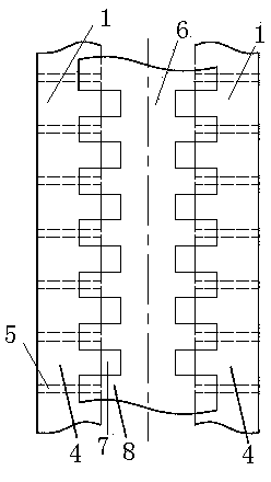
[0034] A method for sub-regional cooling between internal cooling and external cooling of rotor magnetic poles. The cooling gas flows into the channel between the two magnetic pole coils 1 through the ventilation partition device 6 on the air inlet end of the two magnetic pole coils 1 to form an external cooling ventilation air path, and The outside of the pole coil 1 is cooled, and at the same time the cooling gas flows into the inside of the pole coil 1 through the gap between the pole core 2 and the pole coil 1, forming an internal cooling ventilation air path, and cooling the inside of the pole coil 1, and then from the pole coil 1 internally flows into the channel between the two magnetic pole coils 1, and the ventilation partition device 6 separates the external cooling ventilation air path and the internal cooling ventilation air path flowing into the channel from each other.
[0035]The magnetic pole coil 1 is formed by stacking multi-layer current-carrying bars 4, and ...
Embodiment 3
[0038] A method for sub-regional cooling between internal cooling and external cooling of rotor magnetic poles. The cooling gas flows into the channel between the two magnetic pole coils 1 through the ventilation partition device 6 on the air inlet end of the two magnetic pole coils 1 to form an external cooling ventilation air path, and The outside of the pole coil 1 is cooled, and at the same time the cooling gas flows into the inside of the pole coil 1 through the gap between the pole core 2 and the pole coil 1, forming an internal cooling ventilation air path, and cooling the inside of the pole coil 1, and then from the pole coil 1 internally flows into the channel between the two magnetic pole coils 1, and the ventilation partition device 6 separates the external cooling ventilation air path and the internal cooling ventilation air path flowing into the channel from each other.
[0039] The magnetic pole coil 1 is formed by stacking multi-layer current-carrying bars 4, and...
PUM
 Abstract
Description
Claims
Application Information
 - R&D
- Intellectual Property
- Life Sciences
- Materials
- Tech Scout
- Unparalleled Data Quality
- Higher Quality Content
- 60% Fewer Hallucinations
Browse by: Latest US Patents, China's latest patents, Technical Efficacy Thesaurus, Application Domain, Technology Topic, Popular Technical Reports.
© 2025 PatSnap. All rights reserved.Legal|Privacy policy|Modern Slavery Act Transparency Statement|Sitemap|About US| Contact US: help@patsnap.com


