Ventilation control system for laboratory

A ventilation control system and laboratory technology, applied in heating and ventilation control systems, ventilation systems, heating and ventilation safety systems, etc., can solve problems such as increasing ventilation resistance, increasing power input, complex structure, etc., to reduce adverse effects, Good energy-saving effect and the effect of maintaining air pressure balance

Inactive Publication Date: 2015-12-02
LANZHOU UNIVERSITY
View PDF9 Cites 8 Cited by
  • Summary
  • Abstract
  • Description
  • Claims
  • Application Information

AI Technical Summary

Problems solved by technology

The present invention reduces the temperature difference between the intake air temperature and the indoor temperature by exchanging energy between the air inlet air passage and the air outlet air passage, thereby reducing the influence of the outdoor temperature on the indoor temperature. However, the problem with this structure is that multiple The air inlet and outlet air passages result in a complex structure, and increase the ventilation resistance, thereby increasing the power input of the inlet fan and the outlet fan, and the above structure can only reduce the heat exchange caused by the temperature difference between indoor and outdoor, but cannot realize Adjust air flow function

Method used


Image

  • Ventilation control system for laboratory
  • Ventilation control system for laboratory
  • Ventilation control system for laboratory

Examples


Embodiment Construction

[0027] The present invention will be further described in detail below in conjunction with the accompanying drawings and examples. The following examples are explanations of the present invention and the present invention is not limited to the following examples.

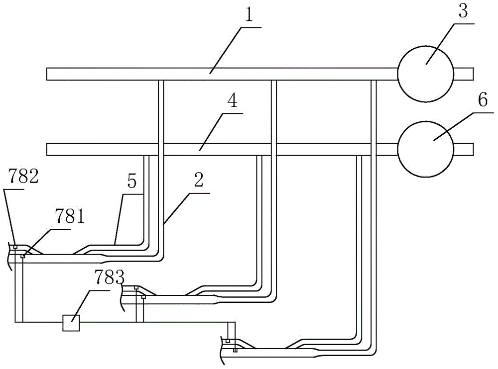
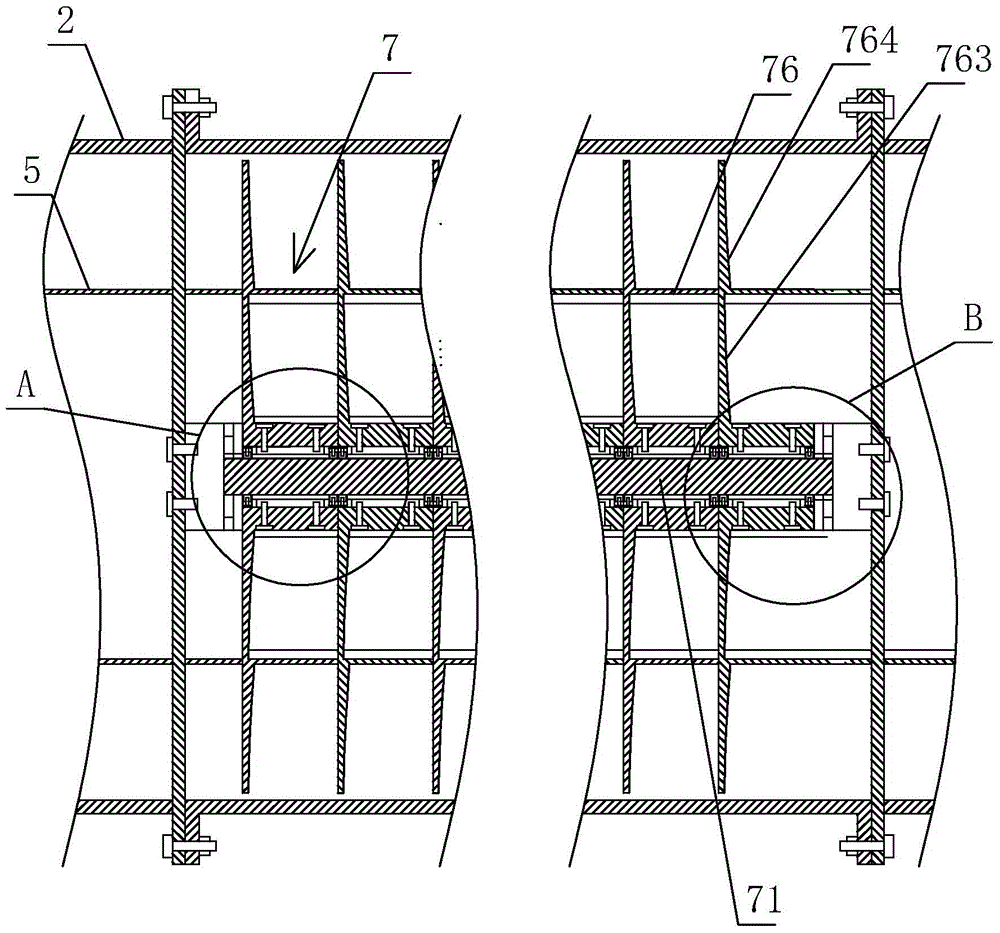
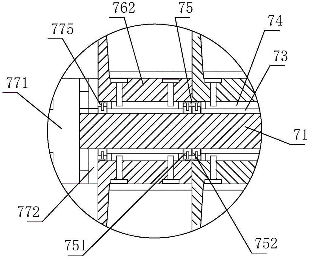
[0028] see Figure 1-Figure 12, the present embodiment is used in a laboratory ventilation control system, including a main air inlet pipe 1, an air inlet pipe branch 2, an air intake device 3, a main exhaust pipe 4, an exhaust pipe branch 5 and an exhaust device 6, The main air inlet pipe 1 is connected to the air inlet 3, the main air inlet pipe 1 is connected to several air inlet pipe branches 2, so as to send the external air into several positions of the laboratory, the main air exhaust pipe 4 is connected to the air exhauster 6, The main exhaust pipe 4 is connected to several exhaust pipe branches 5, so as to discharge the air from several positions in the laboratory to the outside. The air inlet pipe branch 2...


PUM


Abstract

The invention discloses a ventilation control system for a laboratory. The system comprises a main air inflow pipe, an air inflow pipe branch, an air inflow device, a main exhaust pipe, an exhaust pipe branch and an exhaust device and is characterized in that an air adjusting heat exchange segment used for adjusting the air flow and heat exchange is arranged on the exhaust pipe branch and located in the air inflow pipe branch; the air adjusting heat exchange segment comprises a connecting shaft, a first torque motor, a rotating bearing, a gear sleeve, a transmission gear set and connecting cylinders, and the connecting cylinders are sequentially arranged from left to right. In the rotating process of a plurality of inner air adjusting heat exchange fins, a spiral channel can be formed, the size of the channel and the size of an opening of the channel change regularly, and therefore the air flow of the exhaust pipe branch can be adjusted, and in a similar way, the air inflow of the air inflow pipe branch can be adjusted; in the rotating process of the inner air adjusting heat exchange fins, the contact area of air in the channel and the inner air adjusting heat exchange fins is unceasingly increased, and therefore heat exchange between the exhaust pipe branch and the air inflow pipe branch can be achieved through the inner air adjusting heat exchange fins and outer air adjusting heat exchange fins, and the temperature difference of air in the exhaust pipe branch and air in the air inflow pipe branch is reduced.

Description

technical field [0001] The invention relates to a ventilation control system for a laboratory. Background technique [0002] The ventilation design requirements of laboratory ventilation and comfort air conditioning systems are different. The main purpose is to provide a safe and comfortable working environment and reduce the possibility of personnel being exposed to dangerous air. Ventilation mainly solves the health and labor protection problems of the working environment for the experimenters. Laboratory ventilation requires all fresh air to come from the outside, and then 100% is exhausted outside, and the exhaust from the fume hood is not circulated indoors. The chemical laboratory requires more than 10 air changes per hour, and the physical laboratory requires more than 10 air changes per hour. When the laboratory is empty, the air change can be reduced to 6 times. The number of laboratory fume hoods should be designed to be sufficient, and should not be used as the ...

Claims


Application Information

Patent Timeline
Patent Type & Authority Applications(China)
IPC IPC(8): F24F7/08F24F11/00
CPCF24F7/08F24F11/0001
Inventor 焦继宗张丽静
Owner LANZHOU UNIVERSITY
Why Eureka
Try Eureka