Photocatalyst filter, photocatalyst filter laminate, exhaust unit, and image forming apparatus

a photocatalyst and filter technology, applied in the direction of physical/chemical process catalysts, metal/metal-oxide/metal-hydroxide catalysts, separation processes, etc., can solve the problems of insufficient heat dissipation of the image forming apparatus in some cases, inability to efficiently decompose etc., to achieve the elimination of ozone gas or voc, efficient decomposition and elimination, and the effect of reducing

Active Publication Date: 2018-01-04
SHARP KK
View PDF9 Cites 2 Cited by
  • Summary
  • Abstract
  • Description
  • Claims
  • Application Information

AI Technical Summary

Benefits of technology

[0010]Since the photocatalyst filter of the present disclosure includes a filter substrate and a photocatalyst layer supported by the filter substrate, ozone gas or VOC in air can be efficiently decomposed and eliminated by irradiating the photocatalyst layer with light and allowing the air containing ozone gas or VOC to pass through the filter.
[0011]The photocatalyst layer supported by the filter substrate exhibits the photocatalytic action by receiving light having a wavelength of 400 nm or more. Accordingly, visible light can be used for decomposing and eliminating ozone gas or

Problems solved by technology

In addition, the toner heated with the fixing device may generate volatile organic compounds (VOC) in some cases.
In known image forming apparatuses, ozone gas or VOC cannot be efficiently decomposed in some cases.
In additi

Method used


Image

  • Photocatalyst filter, photocatalyst filter laminate, exhaust unit, and image forming apparatus
  • Photocatalyst filter, photocatalyst filter laminate, exhaust unit, and image forming apparatus
  • Photocatalyst filter, photocatalyst filter laminate, exhaust unit, and image forming apparatus

Examples


first embodiment

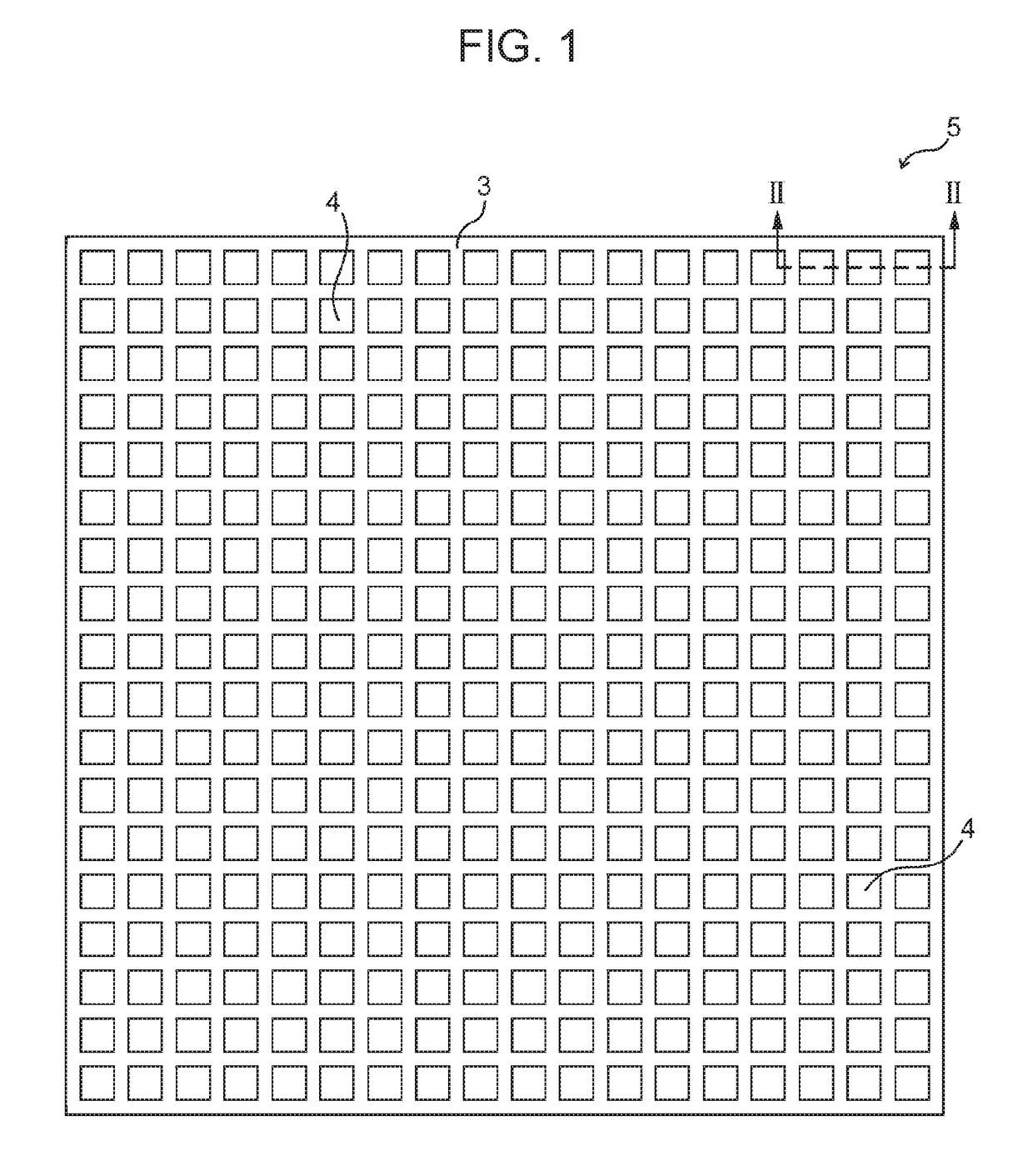
[0036]FIG. 1 is a schematic plan view of a photocatalyst filter of this Embodiment, and FIG. 2 is a schematic cross-sectional view of the photocatalyst filter taken along the broken line II-II of FIG. 1.

[0037]The photocatalyst filter 5 of the Embodiment includes a sheet-like filter substrate 1 and a photocatalyst layer 3 supported by the filter substrate 1. The photocatalyst layer 3 exhibits a photocatalytic action by receiving light having a wavelength of 400 nm or more, and the photocatalyst filter 5 has an aperture ratio of 35% or more and 80% or less.

[0038]The photocatalyst filter 5 of the Embodiment can be applied to, for example, an air cleaner, a gas treatment apparatus, a deodorizing apparatus, and a sterilization (antibacterial) apparatus. Furthermore, the photocatalyst filter 5 can provide additional functions to application products, such as a vacuum cleaner, a washing machine, a lighting system, an air conditioner, and a copier. The photocatalyst filter 5 of Second Embod...

second embodiment

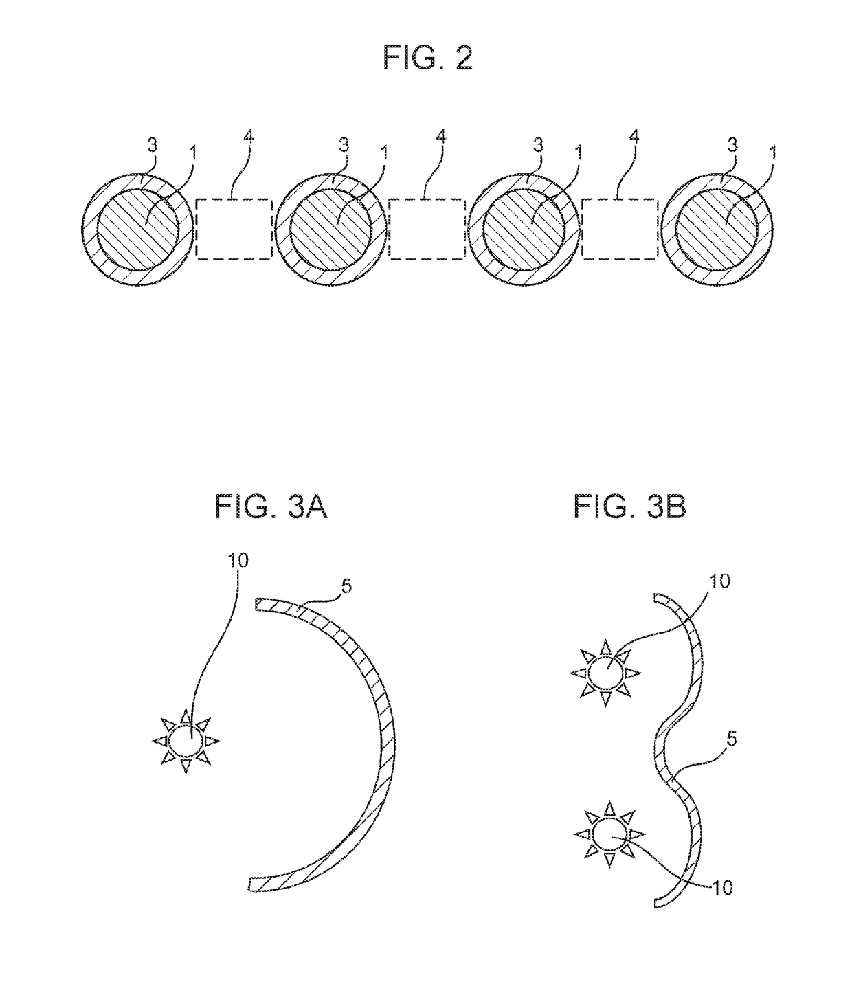
[0054]FIGS. 3A and 3B are schematic cross-sectional views of photocatalyst filters 5 of this Embodiment. The photocatalyst filters 5 of the Embodiment have curved shapes. Except this point, the configuration is the same as that of the photocatalyst filter 5 of First Embodiment.

[0055]The filter substrate 1 included in the photocatalyst filter 5 of the Embodiment can be wire netting, punching metal, or expand metal. These metal materials have high workability and allow the photocatalyst filter 5 to be bent.

[0056]The photocatalyst filter 5 can be bent such that the concave surface of the photocatalyst filter 5 is irradiated with light from a light source section 10. This can reduce the unevenness in the amount of light received by the photocatalyst filter 5 and can enhance the ability of decomposing ozone gas or VOC.

[0057]The photocatalyst filter 5 can have a curved surface such that the distance from the light source section 10 to the photocatalyst filter 5 is substantially constant. ...

third embodiment

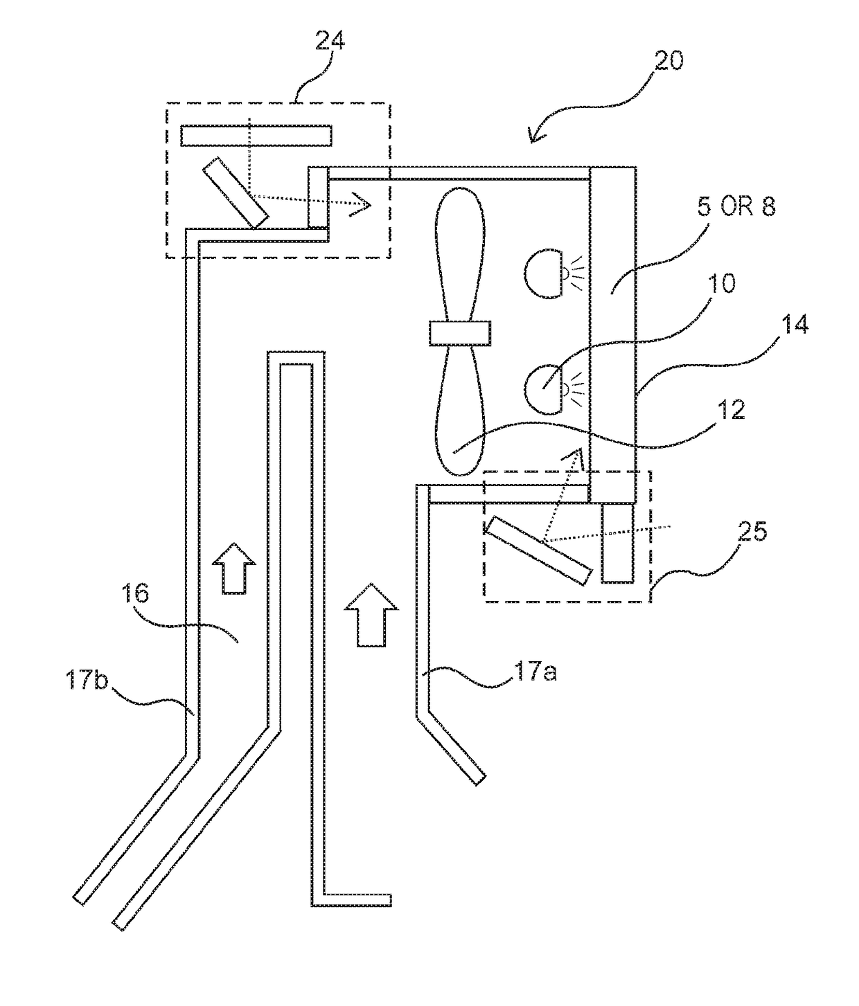
[0059]FIG. 4 is a schematic cross-sectional view of a photocatalyst filter laminate 8 of this Embodiment. The photocatalyst filters 5 included in the photocatalyst filter laminate 8 of the Embodiment are the same as the photocatalyst filter 5 of First Embodiment.

[0060]The photocatalyst filter laminate 8 of the Embodiment can be applied to, for example, an air cleaner, a gas treatment apparatus, a deodorizing apparatus, and a sterilization (antibacterial) apparatus. Furthermore, the photocatalyst filter laminate 8 can provide additional functions to application products, such as a vacuum cleaner, a washing machine, a lighting system, an air conditioner, and a copier. The photocatalyst filter laminate 8 of Fourth Embodiment is also the same.

[0061]The photocatalyst filter laminate 8 has a structure where a plurality of photocatalyst filters 5 are stacked. The stacking of the photocatalyst filters 5a to 5d increases the probability that ozone gas or VOC contained in the air that is allo...


PUM

PropertyMeasurementUnit
Fractionaaaaaaaaaa
Fractionaaaaaaaaaa
Thicknessaaaaaaaaaa

Abstract

The present disclosure provides a photocatalyst filter that can efficiently decompose and eliminate ozone gas or VOC and has a low ventilation resistance. The photocatalyst filter includes a sheet-like filter substrate and a photocatalyst layer supported by the filter substrate. The photocatalyst layer exhibits a photocatalytic action by receiving light having a wavelength of 400 nm or more. The photocatalyst filter has an aperture ratio of 35% or more and 80% or less.

Description

BACKGROUND1. Field[0001]The present disclosure relates to a photocatalyst filter, a photocatalyst filter laminate, an exhaust unit, and an image forming apparatus.2. Description of the Related Art[0002]In an image forming apparatus utilizing a photoreceptor, in general, a charger charges the photoreceptor; an exposure unit forms an electrostatic latent image on the surface of the photoreceptor; and a developing device allows a toner to adhere to the electrostatic latent image to form a toner image on the surface of the photoreceptor. The toner image is then transferred from the photoreceptor to paper that has been fed, and a fixing device heats the paper on which the toner image has been transferred to fix the toner image to the paper. Furthermore, a cleaning unit removes the residual toner on the photoreceptor.[0003]In some cases, for example, the charger may generate ozone gas or NOx. In addition, the toner heated with the fixing device may generate volatile organic compounds (VOC...

Claims


Application Information

Patent Timeline
IPC IPC(8): B01J35/00B01J35/06B01J35/04B01J37/34B01D53/34
CPCB01J35/004B01J35/06B01D53/34B01J37/345B01J35/04B01J37/0219B01J23/6527B01D53/66B01D2255/802B01D2257/708B01D2259/802Y02A50/20
Inventor SHIBAI, YASUHIROONDA, HIROSHITSUTSUMINO, TOMOYA
Owner SHARP KK
Why Eureka
Try Eureka