A piezoelectric device drive circuit
A piezoelectric device and drive circuit technology, applied in electrical components, power oscillators, etc., can solve the problems of high power consumption, high cost, large size, etc., and achieve the effects of low power consumption, small size, and simple circuit structure
- Summary
- Abstract
- Description
- Claims
- Application Information
AI Technical Summary
Problems solved by technology
Method used
Image

Examples
Embodiment 1
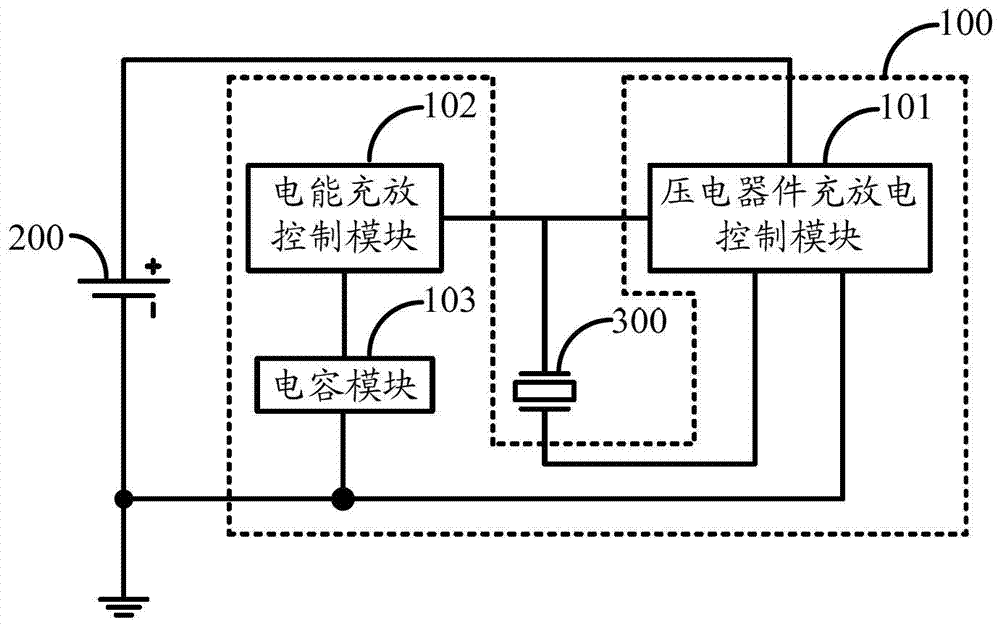
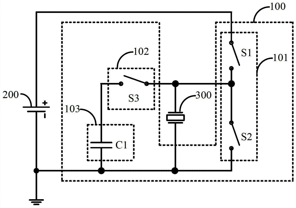
[0027] figure 2 An example circuit structure of the piezoelectric device driving circuit provided by the first embodiment of the present invention is shown. For the convenience of description, only the parts related to the present invention are shown, and the details are as follows:
[0028] The piezoelectric device charge and discharge control module 101 includes a first switch S1 and a second switch S2, the electric energy charge and discharge control module 102 is a third switch S3, and the capacitor module 103 is a first capacitor C1;
[0029] The first terminal of the first switch S1 is connected to the positive pole of the DC power supply 200, the second terminal of the first switch S1 and the first terminal of the second switch S2 are jointly connected to the first terminal of the piezoelectric device 300, and the second terminal of the second switch S2 The two terminals are connected to the negative pole of the DC power supply 200 and the second terminal of the piezoe...
Embodiment 2
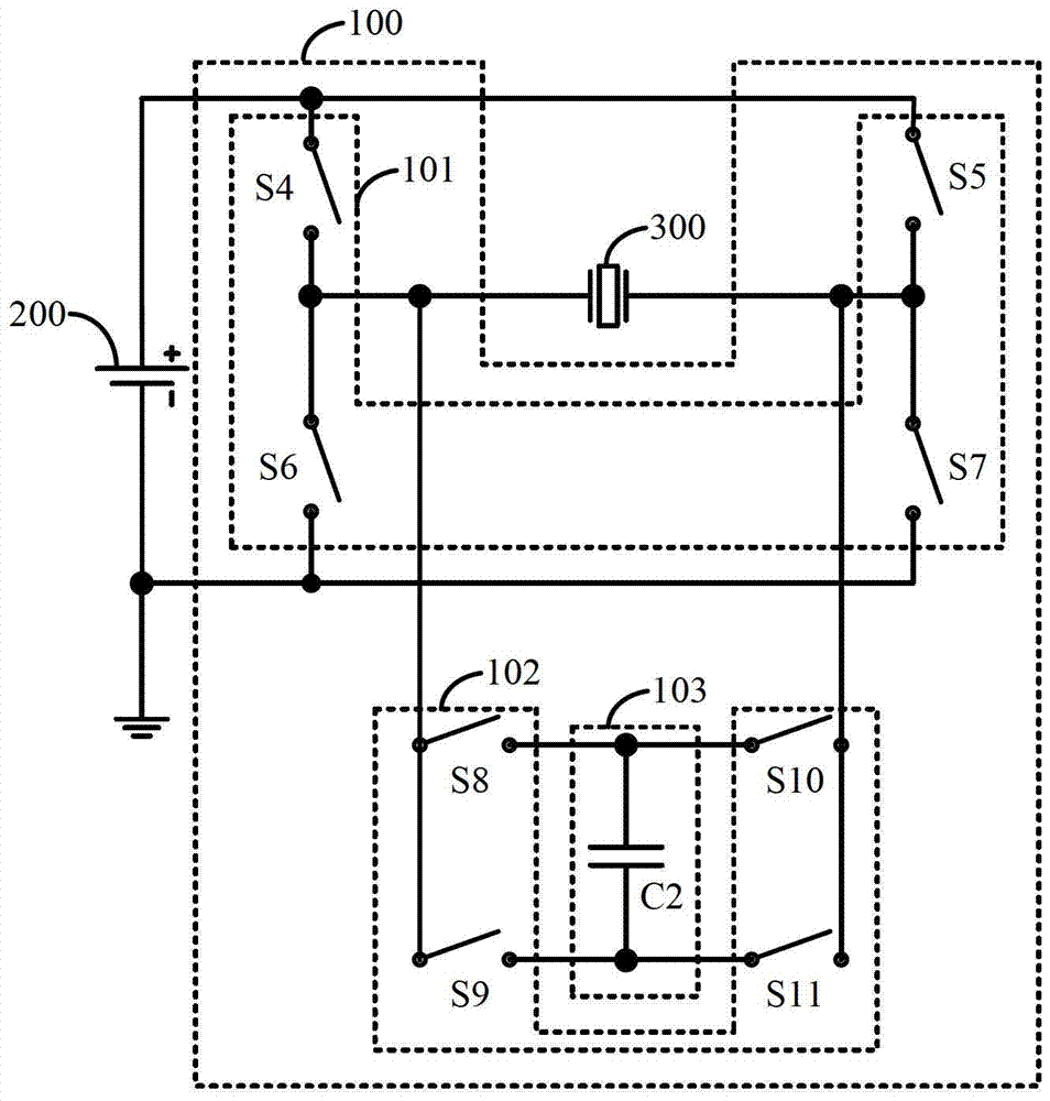
[0040] image 3 An example circuit structure of the piezoelectric device driving circuit provided by the second embodiment of the present invention is shown. For the convenience of description, only the parts related to the present invention are shown, and the details are as follows:
[0041] The piezoelectric device charge and discharge control module 101 includes a fourth switch S4, a fifth switch S5, a sixth switch S6, and a seventh switch S7, and the electric energy charge and discharge control module 102 includes an eighth switch S8, a ninth switch S9, and a tenth switch S10. and the eleventh switch S11, the capacitor module 103 is the second capacitor C2.
[0042] The first terminal of the fourth switch S4 and the first terminal of the fifth switch S5 are commonly connected to the positive pole of the DC power supply 200, and the second terminal of the fourth switch S4 and the first terminal of the sixth switch S6 are commonly connected to the piezoelectric device 300 T...
Embodiment 3
[0057] Figure 4 An example circuit structure of the piezoelectric device driving circuit provided by the third embodiment of the present invention is shown. For the convenience of description, only the parts related to the present invention are shown, and the details are as follows:
[0058] The piezoelectric device charging and discharging control module 101 includes a twelfth switch S12 and a thirteenth switch S13, the electric energy charging and discharging control module 102 includes a fourteenth switch S14 and a fifteenth switch S15, and the capacitor module 103 includes a third capacitor C3, a Four capacitors C4, a sixteenth switch S16 and a seventeenth switch S17.
[0059] The first end of the twelfth switch S12 is connected to the positive pole of the DC power supply 200, the second end of the twelfth switch S12 and the first end of the thirteenth switch S13 are jointly connected to the first end of the piezoelectric device 300, and the thirteenth switch S12 is conne...
PUM
 Abstract
Description
Claims
Application Information
 - R&D
- Intellectual Property
- Life Sciences
- Materials
- Tech Scout
- Unparalleled Data Quality
- Higher Quality Content
- 60% Fewer Hallucinations
Browse by: Latest US Patents, China's latest patents, Technical Efficacy Thesaurus, Application Domain, Technology Topic, Popular Technical Reports.
© 2025 PatSnap. All rights reserved.Legal|Privacy policy|Modern Slavery Act Transparency Statement|Sitemap|About US| Contact US: help@patsnap.com