
Extensible type chip mounter

A technology of placement machine and placement head, which is applied in the direction of assembling printed circuits with electrical components, etc., can solve the problem that the coaxiality of the stepping motor and the suction pen is difficult to ensure, the adjustment of the chip angle is difficult to achieve, and the lateral size of the placement head is large. problems, to achieve the effect of increasing the maximum placement speed, subtracting the auxiliary placement mechanism, and solving processing problems

Inactive Publication Date: 2014-04-09
CHANGAN UNIV
View PDF6 Cites 5 Cited by
  • Summary
  • Abstract
  • Description
  • Claims
  • Application Information

AI Technical Summary

Problems solved by technology

[0004] Moreover, it is difficult to adjust the angle of the chip. The commonly used structures include the following types: 1) Two sets of stepping motors-synchronous belt form, one set is used to feed the placement head to the vertical direction, and the other set is used to adjust The angle of the chip obviously has a large overall structure; 2) The form of stepping motor-reduction device, this form of stepping motor and suction pen is difficult to guarantee the coaxiality, which will reduce the mounting accuracy;
[0005] In addition, the current simple placement machine basically does not realize the automatic feeding of components and parts, and fails to realize automation, which greatly affects the placement efficiency; and the lateral size of the placement head is relatively large, so that a placement machine can only be equipped with one to Two placement heads greatly affect the improvement of placement speed

Method used


Image

  • Extensible type chip mounter
  • Extensible type chip mounter
  • Extensible type chip mounter

Examples


Embodiment Construction

[0048] Specific embodiments of the present invention are given below. It should be noted that the present invention is not limited to the following specific embodiments, and all equivalent transformations made on the basis of the technical solutions of the present application fall within the protection scope of the present invention.

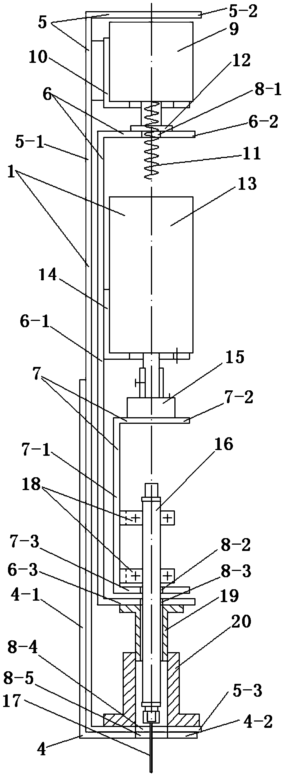
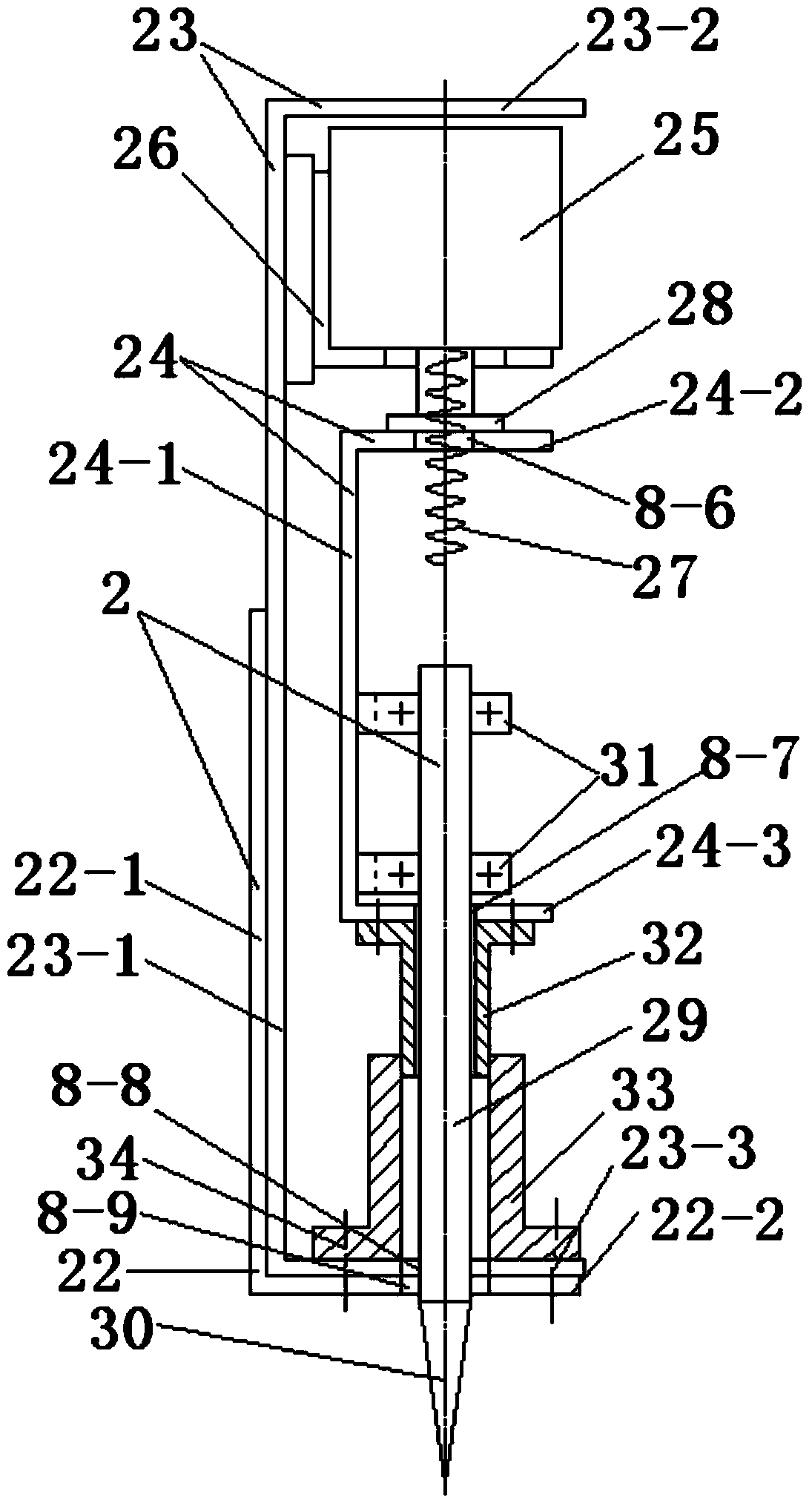
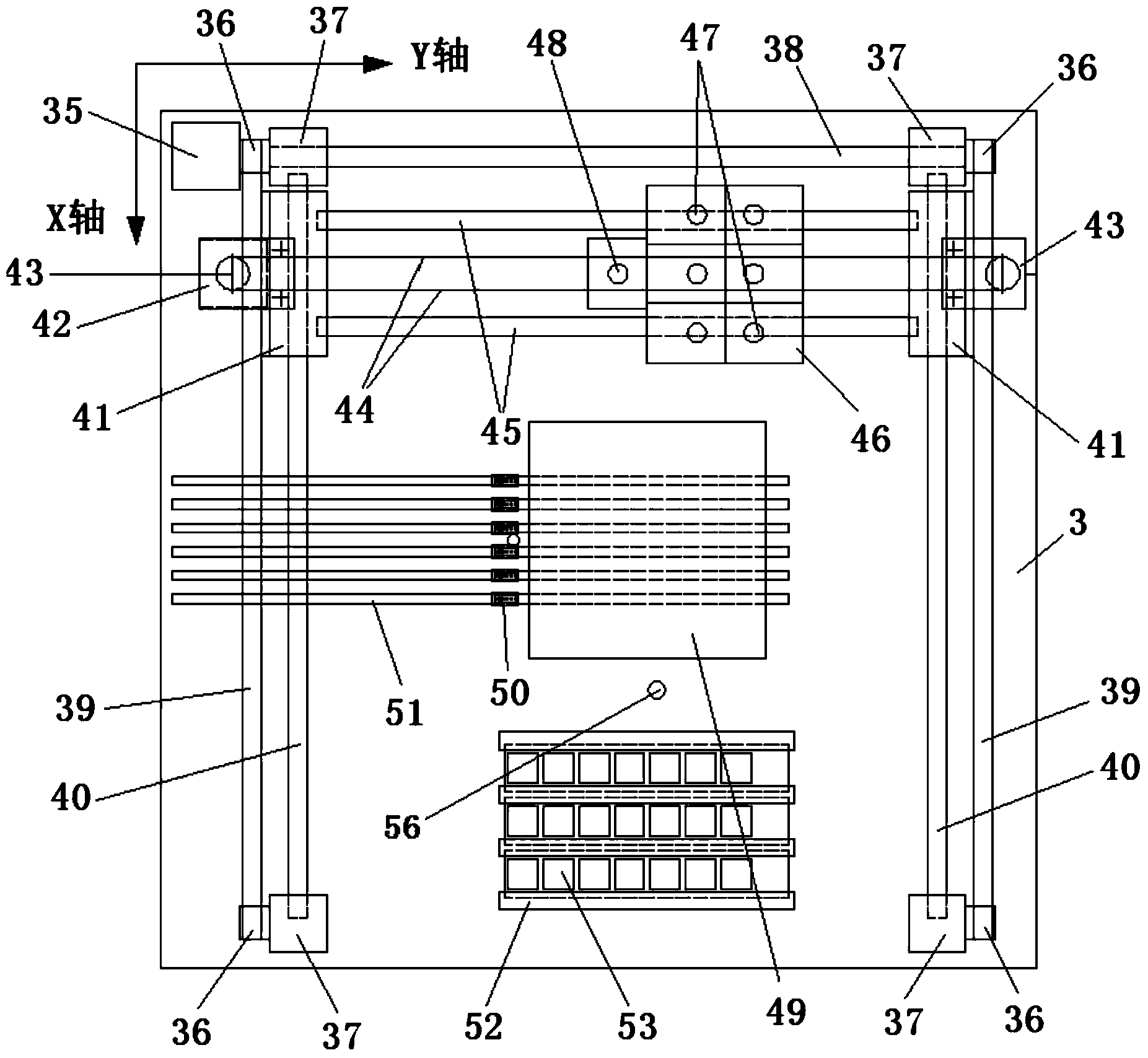
[0049] Follow the above technical solutions, such as Figure 1 to Figure 9 As shown, this embodiment provides an expandable placement machine, which includes a placement head 1. The placement head includes a connecting seat 4, a supporting seat 5, and a lifting guide seat 6, and the connecting seat 4 It includes an "L"-shaped frame composed of a connecting seat back plate 4-1 and a connecting seat bottom plate 4-2 at the bottom end. The supporting seat 5 includes a supporting seat back plate 5-1 and a supporting seat top plate 5-2 at both ends and A "U"-shaped frame composed of the support base plate 5-3, the lifting guide base 6 includes the lifti...


PUM


Abstract

The invention provides an extensible type chip mounter. Through the adoption of a '6+1' extensible mode, the extensible type chip mounter comprises six mounting heads, one dragging head and a mounting platform base. The mounting heads are structurally characterized in that linear stepping motors and speed reduction stepping motors are vertically arranged, and through the arrangement, the linear stepping motors and the speed reduction stepping motors can adjust angles of components and parts while vertical feeding is carried out, and transverse sizes of the mounting heads are reduced so that more mounting heads can be configured integrally within confined spaces, and the highest chip mounting speed is greatly increased. Automatic feeding of the chip mounter can be achieved through the dragging head feeding in the vertical direction and moving in the Y-axis direction. The mounting heads and the dragging head are all installed on mounting movable support plates, and linkage of the mounting movable support plates in the X-axis direction and the Y-axis direction can be achieved on the mounting platform base in a synchronous belt drive-optical axis guiding mode.

Description

Technical field [0001] The invention belongs to the field of patch production, and relates to a patch machine, in particular to an expandable patch machine. Background technique [0002] In recent years, with the rapid development of electronic technology and computer technology, people have put forward new requirements for the practicability and aesthetics of electronic products, making electronic products develop towards miniaturization and diversification of functions, so various small electronic components The mounting technology has become a hot topic. At present, due to the high price of Samsung and Siemens placement machines, many small and medium enterprises with small placement volume are discouraged, and manual placement of components such as 0402 is no longer useful. Therefore, a model has been developed to meet the placement requirements of small and medium enterprises. The placement machine has a broad market. At present, although the simple placement machines appe...

Claims


Application Information

Patent Timeline
IPC IPC(8): H05K3/30
Inventor 王国庆张志新张善交
Owner CHANGAN UNIV
Learn More