
Apparatus and method for seafloor stockpiling

A kind of equipment, mud technology, applied in the field of underwater mining, to achieve the effect of avoiding plume leakage

Inactive Publication Date: 2014-04-09
NAUTILUS MINERALS PACIFIC PTY LTD +1
View PDF8 Cites 6 Cited by
  • Summary
  • Abstract
  • Description
  • Claims
  • Application Information

AI Technical Summary

Problems solved by technology

However, seabed drilling and mining technology cannot make seabed mining possible

Method used


Image

  • Apparatus and method for seafloor stockpiling
  • Apparatus and method for seafloor stockpiling
  • Apparatus and method for seafloor stockpiling

Examples


Embodiment Construction

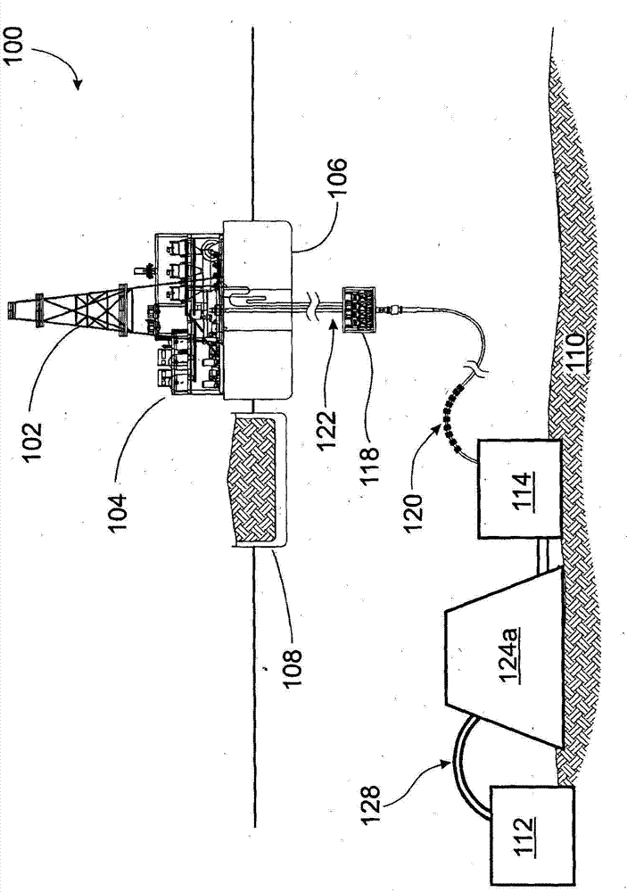
[0033] figure 1is a schematic diagram of an underwater system 100 according to an embodiment of the present invention. The well tower 102 and dewatering equipment 104 are mounted on a surface vessel in the form of an oceangoing production support vessel (PSV) 106 . The PSV has ore handling equipment to load the salvaged ore onto the cargo vessel 108 .

[0034] This embodiment provides the system 100 operable at depths in the vicinity of 2500, however, alternative embodiments may involve operation for depths of 3000 meters or greater. During production operations, one or more seafloor mining tools (SMT) 112 are employed to mine seafloor material, preferably ore, from the seabed 110 .

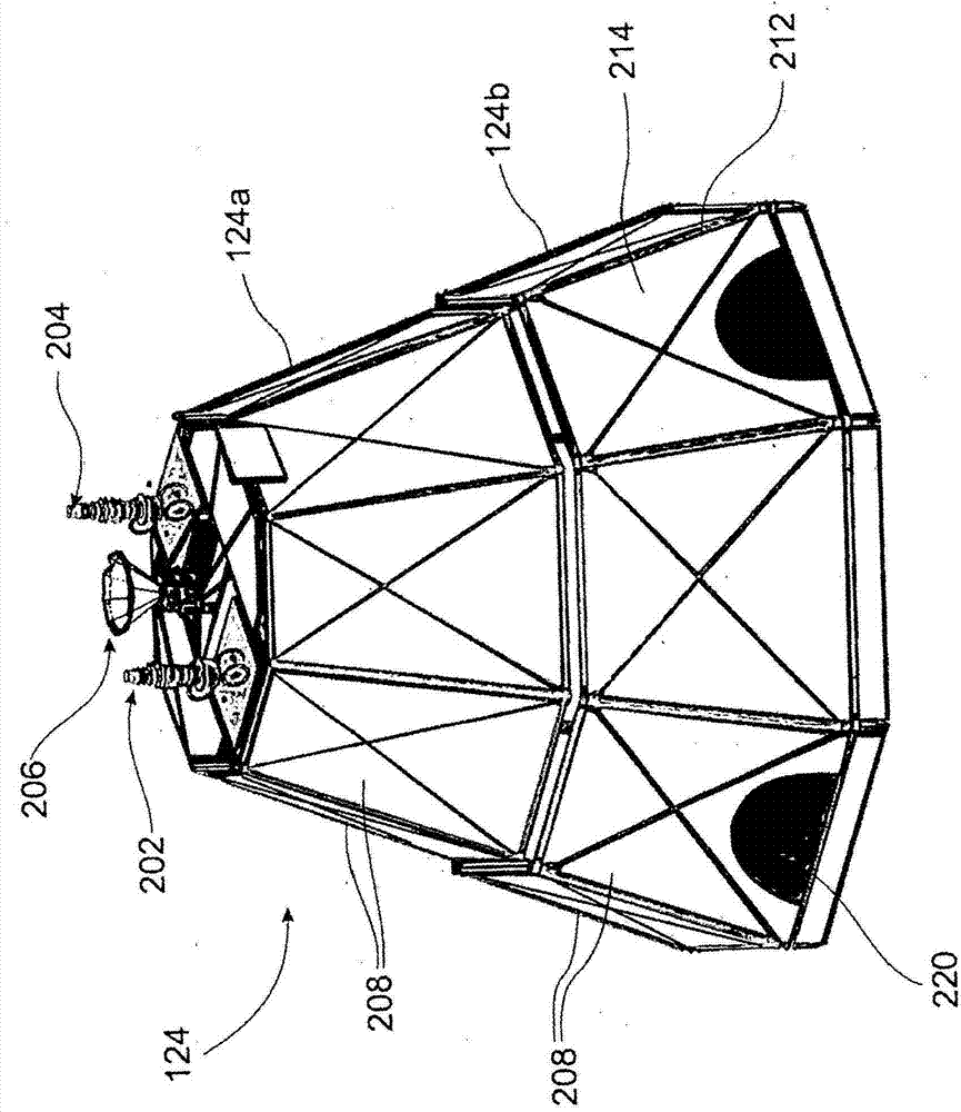
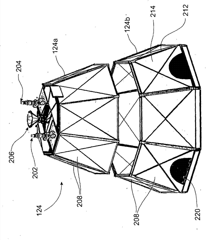
[0035] Ore mined by the seabed mining tool 112 is collected from the seabed mining tool 112 in the form of slurry by cutting and pumping through a stockpile transfer pipe (STP) 128 to a seabed storage facility 124 . The seabed storage facility 124 collects ore from the mud while allowing water...


PUM


Abstract

An apparatus for seafloor stockpiling that has a slurry inlet that receives slurry from a seafloor tool via a slurry transfer pipe and walls that, together with the seafloor, define a cavity having a stockpiling volume. The walls are made substantially of a water permeable material, such as a filter fabric or geotextile, that captures and contains seafloor material present in slurry received from the slurry inlet, while permitting egress of water from the slurry. In a preferred form, the seafloor stockpiling device is a hood with an open bottom that is located on a seafloor surface.

Description

technical field [0001] The present invention relates generally to underwater mining, and more particularly to an apparatus for seabed storage. In particular, the present invention relates to, but is not limited to, a subsea storage facility that receives subsea material (typically a slurry) from at least one subsea tool and through which the subsea storage facility can pass Harvested for transfer to surface vessels. Background technique [0002] Seabed mining is often performed by excavation, for example to salvage valuable alluvial placers or to keep waterways navigable. Suction dredging involves positioning the collection end of a pipe or conduit near the seabed material to be excavated and using a surface pump to create a negative pressure differential to suck water and nearby moving seabed sediment into the pipe. Suction excavation further provides a hinge head located at or near the suction inlet to release compacted earth, gravel or even hard rock that is sucked into...

Claims


Application Information

Patent Timeline
Patent Type & Authority Applications(China)
IPC IPC(8): E21C50/00E21C45/00E02F3/20E02F3/10E02F3/88E02F3/92
CPCE02F3/8858E02F3/8841E02F3/9212E21C50/00E02F7/10E02F5/006E21C45/00E02F3/20E02F3/10E02F3/88E02F3/92
Inventor 格伦·罗伯特·琼斯达尔·哈兰·哲弗兹罗兰·冈特·伯恩德特保罗·戴维·格里菲思戴维·爱德华·米尔本
Owner NAUTILUS MINERALS PACIFIC PTY LTD
Learn More