Spherical rolling and pressing cutter

A rolling knife and ball-shaped technology, applied in the field of machining tools, can solve problems such as uneven force application, affecting the precision and quality of machining, and achieve the effect of avoiding uneven force and improving precision

Active Publication Date: 2014-04-16
宁波市精恒凯翔机械有限公司
View PDF9 Cites 8 Cited by
  • Summary
  • Abstract
  • Description
  • Claims
  • Application Information

AI Technical Summary

Problems solved by technology

[0005] In the existing rolling knife, the rolling head and the tool handle are fixed, and as the processing progresses, uneven force is caused, which affects the processing accuracy and quality

Method used


Image

  • Spherical rolling and pressing cutter
  • Spherical rolling and pressing cutter
  • Spherical rolling and pressing cutter

Examples


Embodiment Construction

[0031] The present invention will be further described in detail below in conjunction with the accompanying drawings and embodiments.

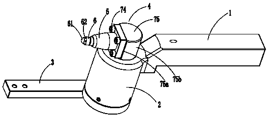
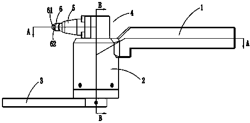
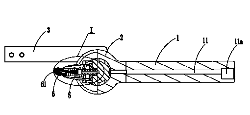
[0032] Such as Figure 1 to Figure 9 Shown is the structural representation of the present invention,

[0033] The reference signs are: tool handle 1, oil inlet passage 11, oil inlet 11a, connector 2, connection passage 21, central body 22, sealing sleeve 23, upper cover 24, guide ring groove 24a, bearing 25, star Type sealing ring 26, oil circuit protection sleeve 27, guide ring 28, guide rod 3, cutter head 4, rolling head 5, oil outlet passage 51, rolling ball retainer 6, external thread 6a, spherical cavity 6b, rolling Ball 61, oil flushing port 62, connecting seat 7, through hole 7a, screw hole 7b, nozzle 71, cone surface 71a, stepped hole 71b, transition sleeve 72, gasket 73, screw 74, rotating head 75, plane 75a, cylinder Surface 75b, shrapnel support ring 81, shrapnel 82, guide sleeve 83, connecting ring 84, and workpiece 9.

[0034]...


PUM


Abstract

The invention discloses a spherical rolling and pressing cutter which comprises a cutter handle, wherein a connecting head is arranged at the head part of the cutter handle; a guide rod connected with a fixing rod on a machine tool is rotatably arranged at one end of the connecting head; a cutter head rotating in the same angle as the guide rod is arranged at the other end of the connecting head; a rolling and pressing head is fixed on the cutter head; a rolling and pressing ball retainer is slantly mounted on the rolling and pressing head; a rolling and pressing ball is mounted at the head part of the rolling and pressing ball retainer in a rolling manner; an oil inlet channel is formed in the cutter handle; an oil inlet is formed in the end part of the oil inlet channel; a connecting channel is formed in the connecting head; an oil outlet channel is formed in the rolling and pressing head; the oil inlet channel, the connecting channel and the oil outlet channel are connected to form an oil passing channel; oil flushing openings are uniformly formed in the periphery of the rolling and pressing ball retainer. The spherical rolling and pressing cutter has the advantage that the cutter head and the guide rod can rotate in the same angle along with machining tracks during a machining process, so that cutting point positions of the rolling and pressing ball and a machined workpiece are always kept unchanged. Thus, the nonuniform stress caused by the changes of the cutting points during the machining process is avoided. As a result, the machining precision is improved.

Description

technical field [0001] The invention relates to the technical field of machining cutters, in particular to a spherical rolling cutter. Background technique [0002] Machine tool processing refers to the processing of raw materials with machine tools. Machine tool processing can be divided into ordinary lathe processing and CNC lathe processing according to different machine tools. With the continuous development of machine tool processing technology, CNC lathes have gradually replaced ordinary lathes. The use of CNC lathe processing not only improves the production effect of parts and products, but also improves the precision of processing to meet the processing needs of fine processing and precision parts. [0003] Rolling knife is a mechanical non-cutting plastic processing method that uses the principle of mechanical extrusion to obtain a mirror-like metal surface. The rolling knife can use the plastic deformation of the metal at room temperature to flatten the microsco...

Claims


Application Information

Patent Timeline
Patent Type & Authority Applications(China)
IPC IPC(8): B23P9/02
CPCB23P9/02
Inventor 李龙江
Owner 宁波市精恒凯翔机械有限公司
Why Eureka
Try Eureka