
Apparatus for on-site detection of holes in tube

An on-site detection and pipeline technology, applied in the direction of material magnetic variables, etc., can solve the problems of complex signal channels, too many detection components, and high price, and achieve the advantages of simple sensing structure, improved sensitivity and signal-to-noise ratio, and good real-time detection. Effect

Inactive Publication Date: 2014-04-16
SHAANXI JOIN CREATE SCI & TECH
View PDF0 Cites 8 Cited by
  • Summary
  • Abstract
  • Description
  • Claims
  • Application Information

AI Technical Summary

Problems solved by technology

The existing detection is mainly imported electromagnetic detector, which is expensive, and often needs to limit the flow rate or flow rate of the fluid in the pipeline to achieve accurate detection, which inevitably limits its scope of use. There is also a wire rope defect detection method. The main problem is that there are too many detection components, the signal channel is complicated, and the acquisition is difficult

Method used


Image

  • Apparatus for on-site detection of holes in tube

Examples


Embodiment Construction

[0009] The present invention will be described in more detail below in conjunction with the accompanying drawings and embodiments.

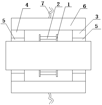
[0010] As shown in the figure, the present invention is a device for on-site detection of holes in pipelines, including a plurality of magnetic gathering rings 1 annularly distributed on the same section, with Hall elements 2 on the magnetic gathering rings 1, each Ring 1 is all positioned between permanent magnet one 3 and permanent magnet two 4, and each permanent magnet one 3 is positioned on the same cross section, and each permanent magnet two 4 is positioned on the same cross section, and permanent magnet one 3 and permanent magnet two 4 different magnetic poles are opposite, permanent Both magnet one 3 and permanent magnet two 4 are connected to the pipeline to be tested through the pole shoe 5 on one side, and the other side of permanent magnet one 3 and permanent magnet two 4 are connected through lining iron 6, and permanent magnet one 3...


PUM


Abstract

The invention relates to an apparatus for on-site detection of holes in tube, which comprises a plurality of magnetism gathering rings annularly distributed on one cross section, a Hall element is provided on the magnetism gathering ring, each magnetism gathering ring is positioned between permanent magnets 1 and permanent magnets 2, each permanent magnet 1 is positioned on one cross section, each permanent magnet 2 is positioned on one cross section, the permanent magnet 1 and the permanent magnet 2 are opposite to a magnetic pole, the permanent magnet 1 and the permanent magnet 2 are connected to a pipeline to be detected through one side pole shoe, the permanent magnet 1 and the other side of the permanent magnet 2 are connected through lining iron, the permanent magnet 1, the permanent magnet 2, the pole shoe and the lining iron form a cavity, the magnetism gathering ring is connected to a soft wire. According to the invention, the detection sensitivity and signal to noise ratio are increased, the system reliability is increased, sensing structure is simple, the detection efficiency is obviously increased, and the on-site real-time detection can be better carried out.

Description

[0001] technical field [0002] The invention relates to the technical field of pipeline damage detection, in particular to a device capable of on-site detection of holes in pipelines. Background technique [0003] Due to wear or corrosion, there are often various perforating damages in the pipeline. For this kind of damage, it cannot be observed with the naked eye outside, and professional inspection tools must be used. The existing detection is mainly imported electromagnetic detector, which is expensive, and often needs to limit the flow rate or flow rate of the fluid in the pipeline to achieve accurate detection, which inevitably limits its scope of use. There is also a wire rope defect detection method. The main problem is that there are too many detection components, the signal channel is complicated, and the acquisition is difficult. Contents of the invention [0004] In order to overcome the disadvantages of the above-mentioned prior art, the object of the present...

Claims


Application Information

Patent Timeline
Patent Type & Authority Applications(China)
IPC IPC(8): G01N27/72
Inventor 不公告发明人
Owner SHAANXI JOIN CREATE SCI & TECH
Learn More