
Array antenna structure for millimeter wave imaging system

A millimeter-wave imaging and array antenna technology, applied in antennas, antenna coupling, antenna arrays, etc., can solve problems such as affecting the imaging quality of the millimeter-wave imaging system and poor isolation of transceiver antennas, reducing near-field electromagnetic interference, reducing The antenna radiation performance is unstable and the effect of improving isolation

Inactive Publication Date: 2014-04-16
SHANGHAI INST OF MICROSYSTEM & INFORMATION TECH CHINESE ACAD OF SCI
View PDF1 Cites 11 Cited by
  • Summary
  • Abstract
  • Description
  • Claims
  • Application Information

AI Technical Summary

Problems solved by technology

[0007] In view of the shortcomings of the prior art described above, the purpose of the present invention is to provide an array antenna structure for a millimeter-wave imaging system, which is used to solve the problem of poor isolation between the transmitting and receiving antennas in the prior art, which affects the imaging of the millimeter-wave imaging system. quality problem

Method used


Image

  • Array antenna structure for millimeter wave imaging system
  • Array antenna structure for millimeter wave imaging system
  • Array antenna structure for millimeter wave imaging system

Examples


Embodiment Construction

[0040] Embodiments of the present invention are described below through specific examples, and those skilled in the art can easily understand other advantages and effects of the present invention from the content disclosed in this specification. The present invention can also be implemented or applied through other different specific implementation modes, and various modifications or changes can be made to the details in this specification based on different viewpoints and applications without departing from the spirit of the present invention.

[0041] see Figure 1 to Figure 7 . It should be noted that the diagrams provided in this embodiment are only schematically illustrating the basic idea of ​​the present invention, and only the components related to the present invention are shown in the diagrams rather than the number, shape and shape of the components in actual implementation. Dimensional drawing, the type, quantity and proportion of each component can be changed arb...


PUM


Abstract

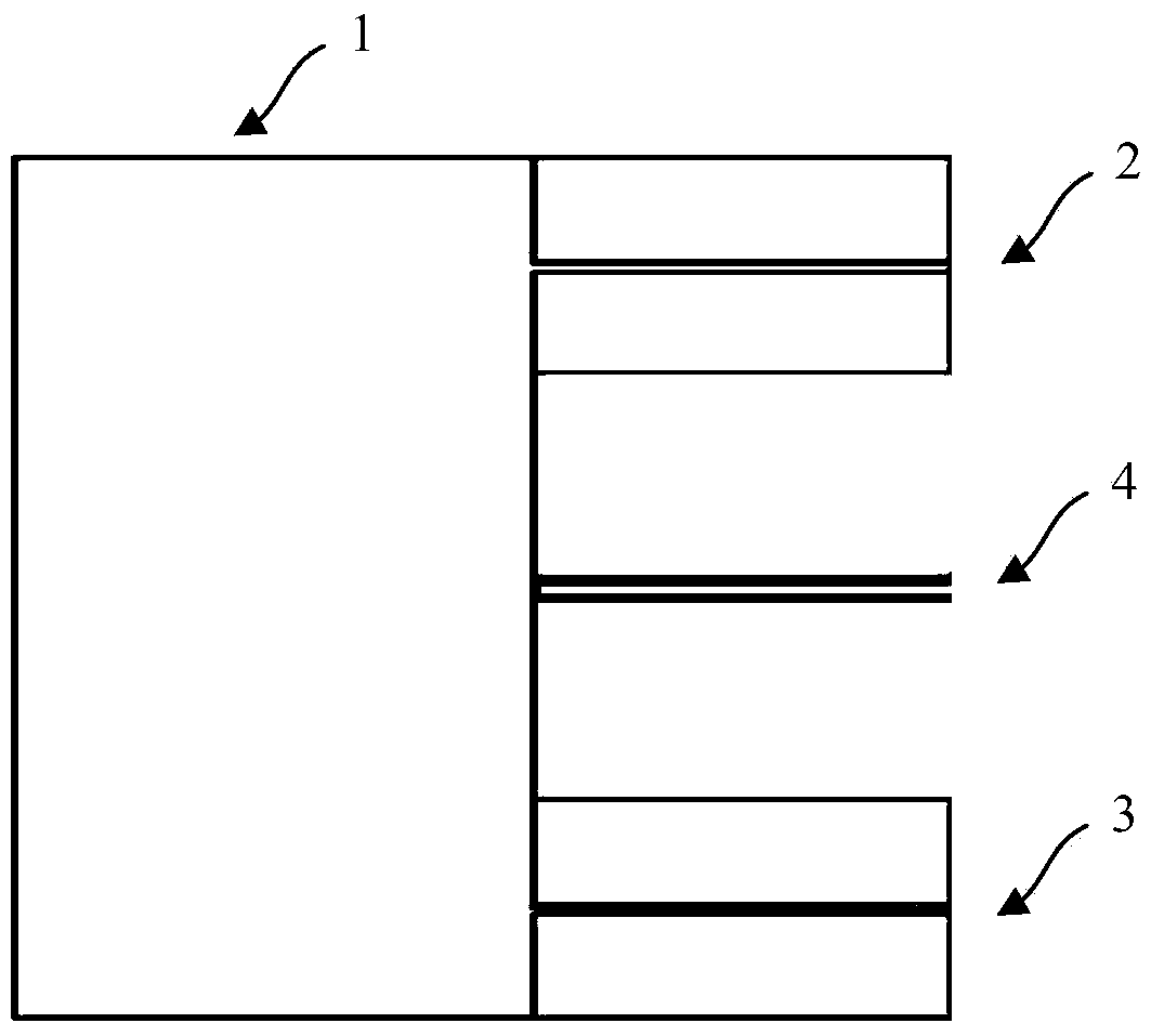
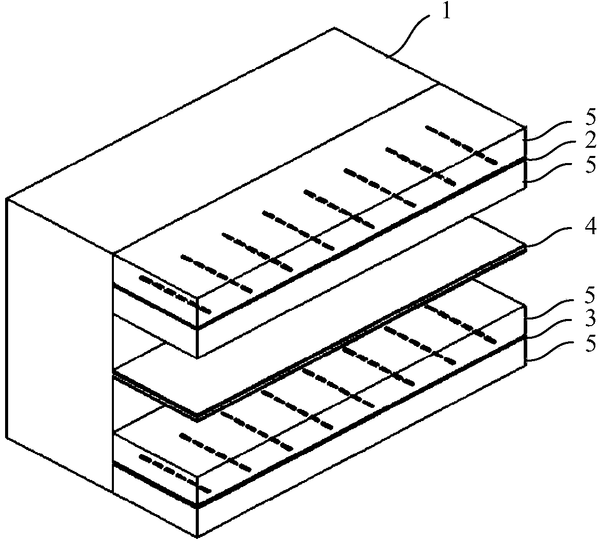
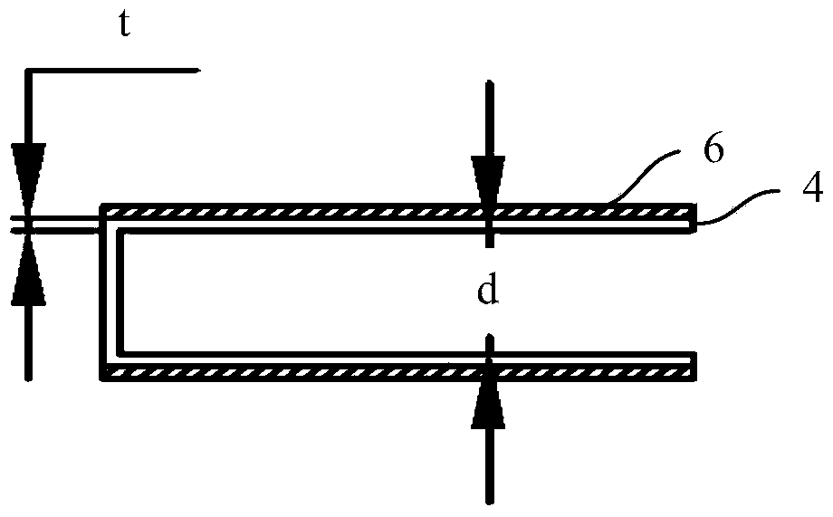
The invention provides an array antenna structure for a millimeter wave imaging system. The array antenna structure for the millimeter wave imaging system comprises a metal cavity, a transmitting antenna array and a receiving antenna array, wherein the transmitting antenna array and the receiving antenna array are located on the same side of the metal cavity in a spaced mode. The array antenna structure further comprises a U-shaped metal isolation structure. The U-shaped metal isolation structure is fixed to the portion, between the transmitting antenna array and the receiving antenna array, of the metal cavity. According to the array antenna structure for the millimeter wave imaging system, the absorptive metal isolation structure is utilized, so that the coupling between a receiving channel and a transmitting channel is obviously reduced, the imaging quality of the imaging system is good, the structure is stable, cost is low, and implementation is easy.

Description

technical field [0001] The invention belongs to the field of millimeter-wave imaging systems, and relates to an array antenna structure for the millimeter-wave imaging system. Background technique [0002] The millimeter-wave imaging system has been developed to the present, and its research content mainly focuses on: the improvement of the performance of the devices used in the millimeter-wave imaging system, the improvement of the scanning structure, the attempt of higher frequency bands, the determination of electromagnetic parameters of various materials, and the improvement of imaging algorithms, etc. . From an application point of view, high-resolution, stable and reliable performance is the development trend of millimeter-wave imaging systems. In order to realize such a system, the improvement of device performance, engineering design method and algorithm is the only way. [0003] The active millimeter-wave imaging system is based on the principle of millimeter-wave...

Claims


Application Information

Patent Timeline
Patent Type & Authority Applications(China)
IPC IPC(8): H01Q1/52H01Q17/00H01Q21/00
Inventor 孙芸孙晓玮杨明辉王志高
Owner SHANGHAI INST OF MICROSYSTEM & INFORMATION TECH CHINESE ACAD OF SCI
Learn More