Francis turbine or francis pump or francis pump turbine

A water turbine and impeller technology, applied in the direction of machines/engines, hydroelectric power generation, mechanical equipment, etc., can solve the problem that the spiral shell is not rotationally symmetrical

Active Publication Date: 2014-04-16
VOITH PATENT GMBH
View PDF8 Cites 2 Cited by
  • Summary
  • Abstract
  • Description
  • Claims
  • Application Information

AI Technical Summary

Problems solved by technology

However, the spiral shell is not ideally rotationally symmetric

Method used


Image

  • Francis turbine or francis pump or francis pump turbine
  • Francis turbine or francis pump or francis pump turbine
  • Francis turbine or francis pump or francis pump turbine

Examples


Embodiment Construction

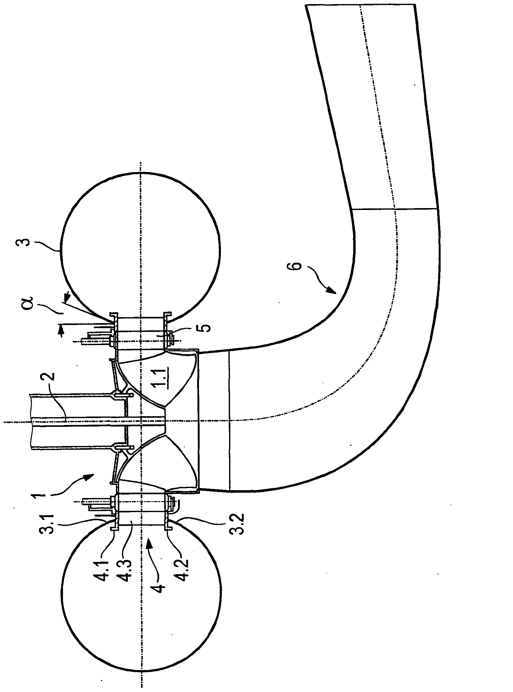
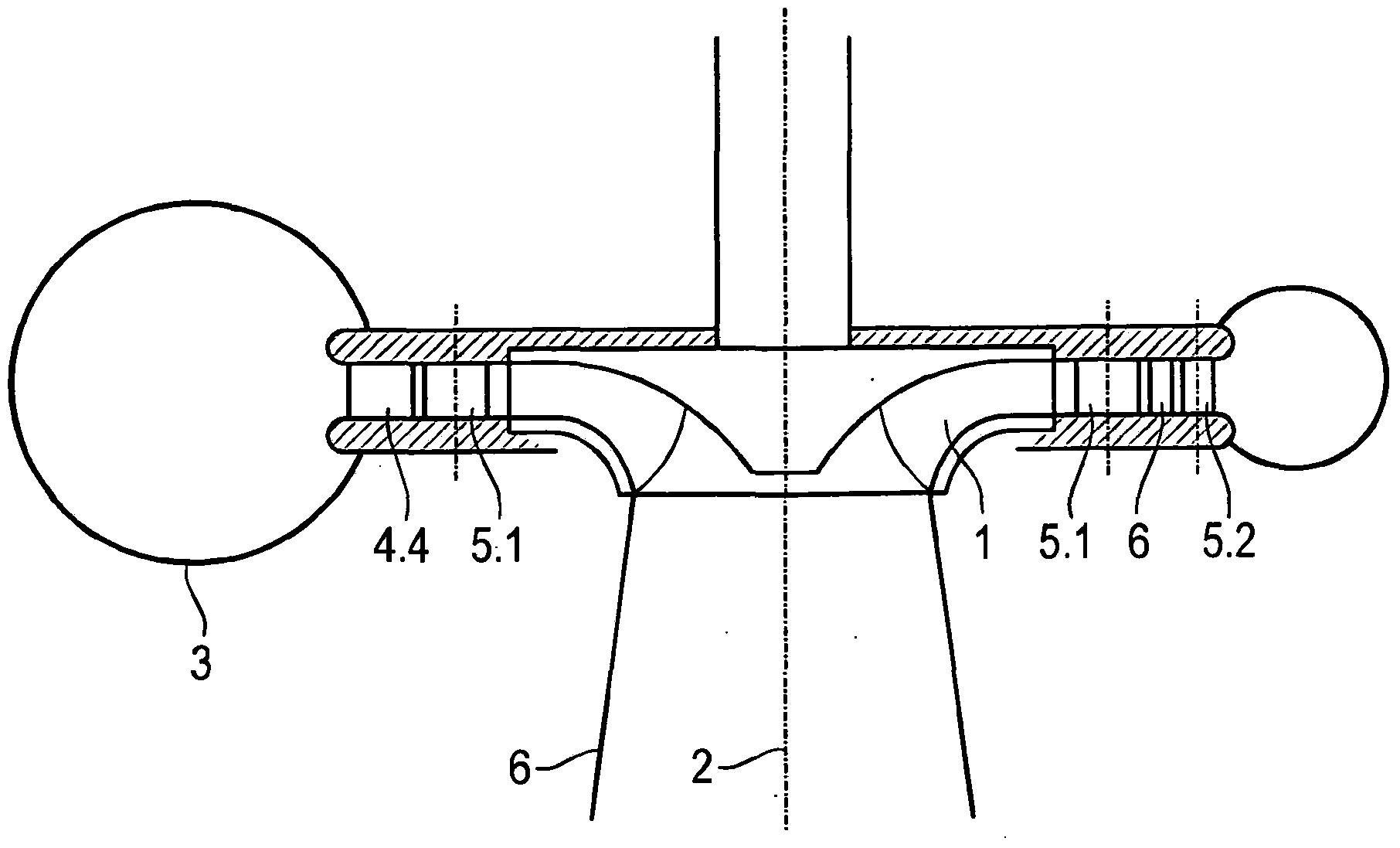
[0018] in figure 1 The Francis turbine shown in has an impeller 1. It includes multiple blades 1.1. The impeller 1 rotates around the rotation axis 2.

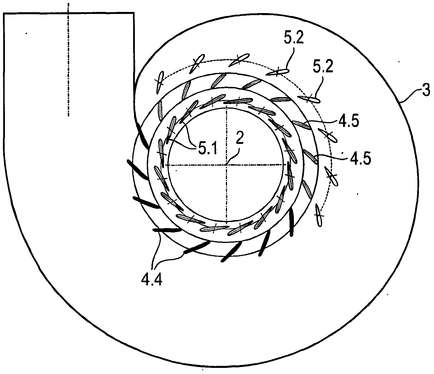
[0019] The impeller 1 is surrounded by a spiral casing 3. The spiral housing 3 has a circular cross section, for example. It has a slit-shaped opening along the circumference opposite to the impeller 1. The opening gap is limited by the edges 3.1, 3.2 along the circumference.

[0020] The beam ring 4 is connected to the gap formed by the edges 3.1, 3.2 along the circumference. The beam ring has two beam ring covers 4.1 and 4.2. The beam 4.3 is used as a tie rod.

[0021] The circumferential edges 3.1 and 3.2 of the spiral shell are welded to the beam ring covers 4.1 and 4.2.

[0022] A guide device with guide blades 5 is arranged between the beam ring and the impeller.

[0023] Viewed from the direction of the water flow, the suction pipe 6 is connected to the impeller 1, and the suction pipe has a plurality of sections.

[0024] ...


PUM


Abstract

The invention relates to a Francis turbine or other machine built according to the Francis principle; with an impeller having rotor blades; with a volute housing that surrounds the impeller; with a traverse ring comprising a number of traverses; with an inner rotor blade ring having larger traverses, which is arranged downstream of the traverse ring. The invention is characterised by the following features: suggested is an outer rotor blade ring that is arranged upstream of the traverse ring; a part of the traverse ring extends with larger traverses over a part of the circumference of the impeller, beginning at the start of the volute, and a part of the traverse ring extends with smaller traverses over the broader circumference of the impeller as far as the end of the volute.

Description

Technical field [0001] The invention relates to a Francis water turbine or Francis pump or Francis water pump turbine, in particular to a guiding device of such a water turbine, which is used to transport water to an impeller. Background technique [0002] For hydraulic turbines such as Francis turbines, higher and higher requirements are put forward in terms of efficiency and the widest possible scope of work. It is expected that the water flow can be variably applied from extreme partial load operation to overload operation. In all load ranges, the highest possible efficiency should be achieved in the vibration-free operation of the turbine. [0003] Francis turbines can adapt to different operating conditions by adjusting the guide blades. However, particularly unstable flow conditions under partial load can cause strong machine vibration. Especially when the natural frequency of the component is consistent with this kind of vibration, material damage will occur. For large m...

Claims


Application Information

Patent Timeline
Patent Type & Authority Applications(China)
IPC IPC(8): F03B3/18F03B11/04F03B3/02
CPCF03B3/02F03B3/18F03B11/04F03B3/186Y02E10/223Y02E10/226F03B3/183F03B3/125Y02E10/20
Inventor 托马斯·凯澈莱马丁·吉泽
Owner VOITH PATENT GMBH
Why Eureka
Try Eureka