Rolling bearing, and spindle device for machine tool

A rolling bearing and roller technology, applied in rolling contact bearings, roller bearings, bearings in rotating motion, etc., can solve problems such as unsatisfactory transmission efficiency and achieve the effect of preventing seizure

Inactive Publication Date: 2014-04-16
NSK LTD
View PDF14 Cites 10 Cited by
  • Summary
  • Abstract
  • Description
  • Claims
  • Application Information

AI Technical Summary

Problems solved by technology

[0002] In the recent development of machine tool spindles, the speed has been continuously pursued in order to improve the efficiency. Due to the influence of heat generated by the friction when the gears mesh with each other and the slippage of the bel

Method used


Image

  • Rolling bearing, and spindle device for machine tool
  • Rolling bearing, and spindle device for machine tool
  • Rolling bearing, and spindle device for machine tool

Examples


Embodiment Construction

[0099] Hereinafter, rolling bearings according to various embodiments of the present invention will be described in detail with reference to the drawings.

[0100] (first embodiment)

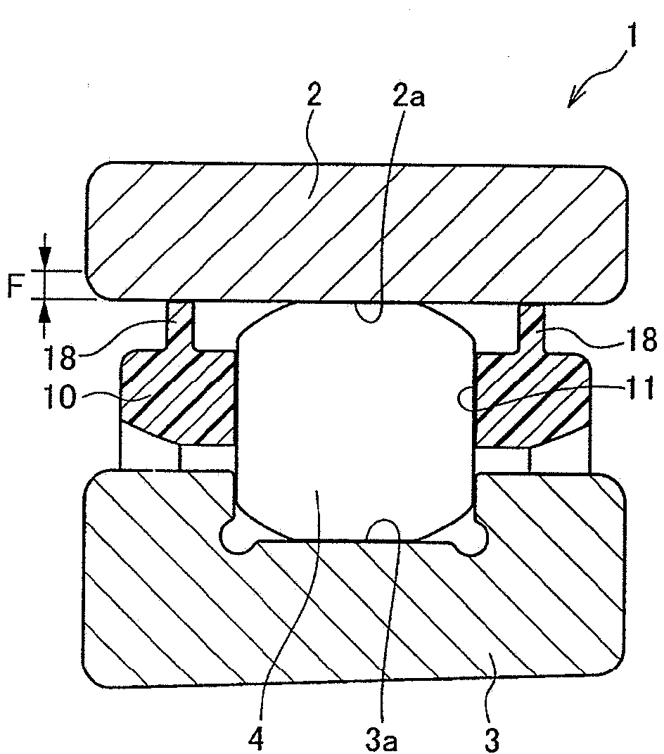
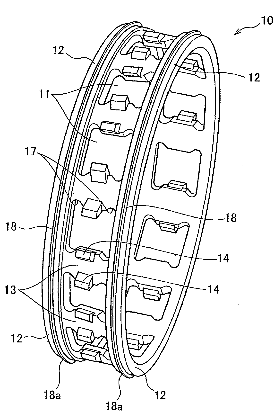
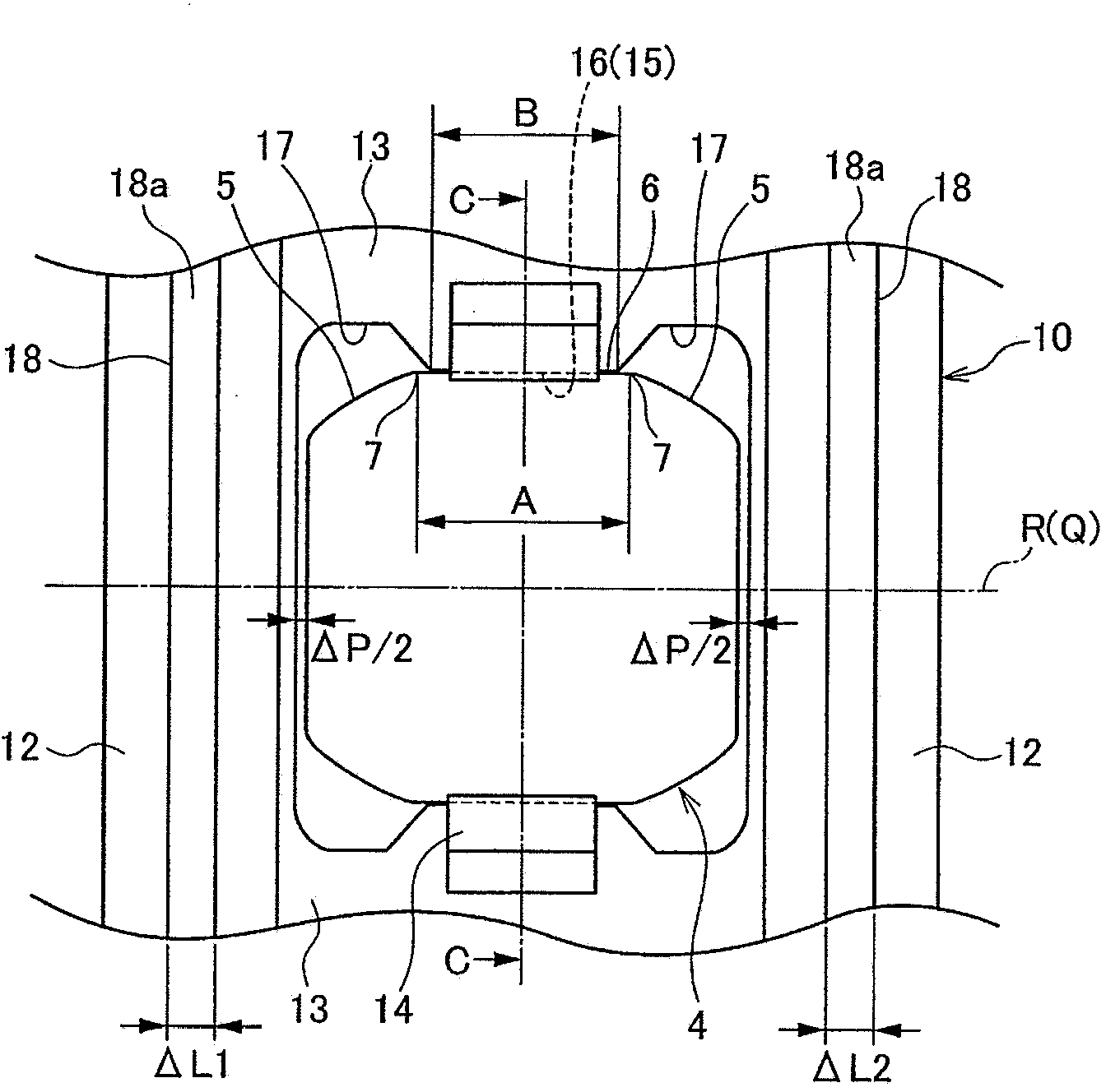
[0101] figure 1 is a sectional view of a rolling bearing according to a first embodiment of the present invention, figure 2 for figure 1 Oblique view of the middle cage, image 3 for figure 1 A plan view of a part of a rolling bearing, Figure 4 for image 3 The C-C section view, Figure 5 (a) is a plan view of the roller, Figure 5 (b) is a plan view of the cage.

[0102] As shown in the figure, the rolling bearing 1 according to the first embodiment of the present invention is provided with an outer ring raceway surface 2a on the inner diameter surface of the outer ring 2, and an inner ring raceway surface on the outer diameter surface of the inner ring 3. 3a, between the raceway surface 2a of the outer ring and the raceway surface 3a of the inner ring, a plurality of rollers (rolling el...


PUM


Abstract

A rolling bearing (1) is provided with an outer ring (2), an inner ring (3), rollers (4) which are provided in a rollable manner between the outer ring (2) and the inner ring (3), and a retainer (10) which has pockets (11) formed at predetermined intervals in the circumferential direction and respectively retaining the rollers (4). The retainer (10) is of the outer ring guide type or the inner ring guide type. The retainer (10) has retainer guide surfaces on one axial side and the other axial side, respectively, of each of the rollers (4). If the width of the retainer guide surface on the one axial side is DeltaL1, the width of the retainer guide surface on the other axial side is DeltaL2, and the gap of an axial pocket is DeltaP, the rolling bearing (1) satisfies the expressions of DeltaP<= DeltaL1<= 4*DeltaP and DeltaP <= DeltaL2 <= 4*DeltaP.

Description

technical field [0001] The present invention relates to a rolling bearing and a machine tool spindle, or more specifically, a spindle used in a high-speed rotary machine tool, a rolling bearing used in a high-speed motor, etc., and a machine tool spindle device using the motor and the like. Background technique [0002] In the recent development of machine tool spindles, high speed has been pursued in order to improve efficiency. In the current gear drive and belt drive, the friction caused by the meshing of the gears and the slippage of the belt are affected by heat generation. The transmission efficiency is not ideal, so the use of a coupling to directly couple the drive motor, or directly set it inside the main shaft, the so-called built-in motor has become the current mainstream. In the case of these high-speed spindles, the dmn value of the bearings used in the spindle has basically reached more than 500,000 revolutions. In addition, when using ceramic materials (such ...

Claims


Application Information

Patent Timeline
IPC IPC(8): F16C33/46B23B19/02F16C19/26
CPCF16C33/46F16C19/26F16C33/6614F16C33/4676F16C33/4605F16C33/36F16C2240/46F16C2322/39F16C43/06F16C2240/50F16C19/527F16C33/34
Inventor 水上敦司
Owner NSK LTD
Why Eureka
Try Eureka