Thermal transfer device with reduced vertical profile

A technology of heat transfer fluid and condenser, which is applied in the field of heat transfer devices with reduced vertical section

Active Publication Date: 2014-04-16
AAVID THERMALLOY LLV
View PDF11 Cites 20 Cited by
  • Summary
  • Abstract
  • Description
  • Claims
  • Application Information

AI Technical Summary

Problems solved by technology

This is one of the biggest limitations of prior art condensers

Method used


Image

  • Thermal transfer device with reduced vertical profile
  • Thermal transfer device with reduced vertical profile
  • Thermal transfer device with reduced vertical profile

Examples


Embodiment Construction

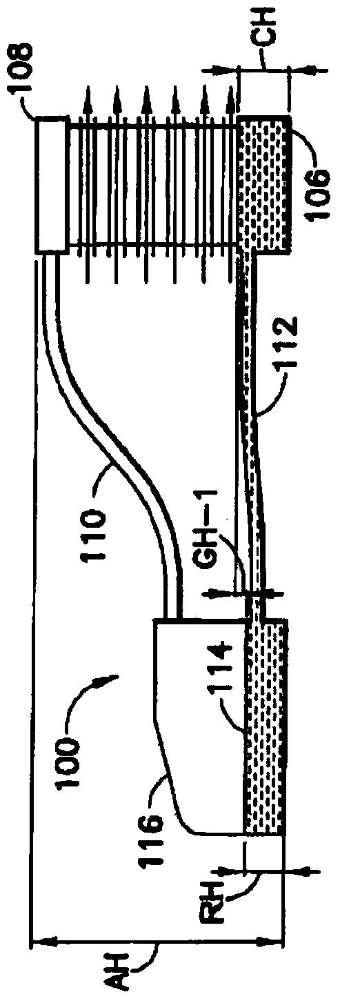
[0034] According to a preferred embodiment of the invention, a heat transfer device or "closed loop fluid cooling system" according to the invention is shown generally at 10 in FIG. 4 . The heat transfer device 10 includes a reservoir 12, which acts as an evaporator, for holding a heat transfer fluid 14, and a first conduit 16, for directing the heat transfer fluid 14 out of the reservoir when the heat transfer fluid is in a vapor state. 12; and a second conduit 18 for directing the heat transfer fluid 14 back to the reservoir 12 once it has been condensed from its vapor state to its liquid state. The maximum height to which the liquid portion of the heat transfer fluid can rise before flooding the condensing surface is designated h in FIG. 4 .

[0035] In a preferred embodiment, heat transfer fluid 14 is water or deionized water. When the design places specific requirements on the cooling fluid, for example, freeze resistance, corrosion resistance, or requires the cooling fl...


PUM


Abstract

A heat transfer device with reduced vertical section. The device includes a condenser with generally vertical internal cooling fins. The inlet directs the heat transfer fluid in vapor state to the top of the cooling fins where the vapor condenses and flows along the fins to the bottom of the condenser. The bottom of the condenser is angled towards the outlet to direct the liquid heat transfer fluid to a reservoir for holding the fluid. Both the inlet and the outlet are arranged at a height above the level of the heat transfer fluid in liquid state in the reservoir. The arrangement may also include fins on the exterior of the condenser to provide a cooling surface that is not in contact with the heat transfer fluid in liquid or vapor state.

Description

technical field [0001] The present invention relates to a heat transfer device, such as a closed loop fluid cooling system, having at least one evaporator, at least one condenser and one or more fluid conduits connecting the evaporator to the condensing connected to a heat transfer device for indirect cooling of an object using a cooling fluid, and more particularly, the present invention relates to a heat transfer device with reduced vertical profile for directing a cooling fluid in a compact environment with Objects to be cooled are in indirect thermal contact. Background technique [0002] Passive closed loop two-phase fluid cooling systems are well known heat transfer devices for cooling objects that generate excessive heat, such as but not limited to computer chips. The term "passive" is intended to mean a system in which cooling fluid is circulated without the use of a mechanical pump. The power used to circulate a fluid in a passive system comes from changes in buoy...

Claims


Application Information

Patent Timeline
Patent Type & Authority Applications(China)
IPC IPC(8): H05K7/20
CPCH01L23/427H01L2924/0002F25B39/04H05K7/20336H05K7/20318H01L2924/00
Inventor 苏克温德·辛格·康约翰·拉尔夫·琴纳莫布雷德利·罗伯特·惠特尼
Owner AAVID THERMALLOY LLV
Why Eureka
Try Eureka