Fertilizer applicator

A fertilizer applicator and fertilization device technology, applied in fertilization devices, fertilizer distributors, agriculture, etc., can solve the problem of no farm manure fertilizer applicator, etc., and achieve the effect of fast fertilization, high work efficiency and low price

Active Publication Date: 2014-04-23
大庆同方农业科技有限公司
View PDF7 Cites 3 Cited by
  • Summary
  • Abstract
  • Description
  • Claims
  • Application Information

AI Technical Summary

Problems solved by technology

In addition, there are fertilizer spreaders, but the existing fertilizer spreaders are all designed for granular chemical fertilizers, and there is no fertilizer spreader that is very suitable for farmyard manure.

Method used


Image

  • Fertilizer applicator
  • Fertilizer applicator
  • Fertilizer applicator

Examples


Embodiment 1

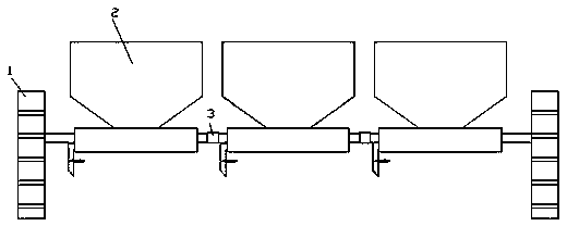
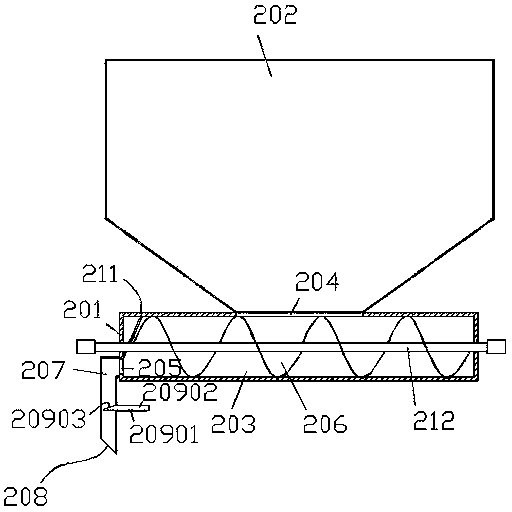
[0026] Embodiment 1, see attached figure 1 , 2 , a fertilizing machine, comprising two wheels 1, a plurality of fertilizing devices 2 arranged between the two wheels 1, two adjacent fertilizing devices 2 are connected by a connecting device 3 to realize series connection, and the fertilizing devices 2 include conveying The box body 201 and the fertilizer storage hopper 202 arranged on the delivery box body 201, the delivery box body 201 is provided with a delivery cavity 203, a fertilizer inlet 204 connecting the delivery cavity 203 and the fertilizer storage hopper 202 And the end outlet 205 that communicates with the delivery cavity 203, the width of the fertilizer inlet 204 can be set according to actual needs, and can be as wide as the delivery cavity 203, and the delivery cavity 203 is provided with two ends extending out of the delivery cavity The driving shaft 212 of 203 and the conveying auger 206 fixed on the driving shaft 212, the connecting device is a coupling, an...

Embodiment 2

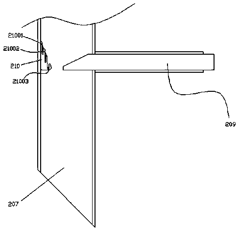
[0027] Embodiment 2, see attached image 3 , the fertilization pipe 207 is provided with an elastic stopper 210 facing downwards from the insertion plate 20902, the elastic stopper 210 is provided with an inclined surface, and the inclined surface is provided with a first groove 21001 and a second groove 21001. The groove 21002 and the third groove 21003, and the first groove 21001, the second groove 21002 and the third groove 21003 gradually deepen as they get closer to the depth of the board 20902, and the elastic stopper 210 and the board together , to control the amount of fertilizer going out, and at the same time, the three grooves can make the elastic stopper have enough elasticity.

Embodiment 3

[0028] Embodiment 3, see attached Figure 4 The fertilizer output control device 209 includes a vertical plate 20904 fixed on the fertilizer output pipe 207, a vertical plate inserted in the vertical plate 20904 and the lower end of which extends into the fertilizer output pipe 207. Insertion plate 20905 is provided with screws for fixing the vertical difference inserting plate 20905 on the vertical plate; the vertical inserting plate is plugged into the fertilizer outlet pipe 207 to control the amount of fertilizer going out from the fertilizer outlet pipe, which can be controlled according to needs or not control.


PUM


Abstract

The invention discloses a fertilizer applicator. The fertilizer applicator comprises two wheels and a plurality of fertilizer application devices which are arranged between the two wheels, wherein every two adjacent fertilizer application devices are connected with each other through a connecting device; each fertilizer application device comprises a conveying box body and a fertilizer storage hopper which is arranged on the conveying box body, wherein the conveying box body is provided with a conveying cavity, a fertilizer inlet which is used for communicating the conveying cavity and the fertilizer storage hopper and an end port outlet which is communicated with the conveying cavity, and the conveying cavity is provided with a driving shaft with two ends stretching out of the conveying cavity and a conveying auger which is fixed on the driving shaft. The fertilizer applicator is simple in structure, low in cost, capable of applying the farmyard manure and chemical fertilizer, high in fertilizer application speed, uniform for applying the fertilizer and high in working efficiency.

Description

technical field [0001] The invention relates to the technical field of agricultural machinery, in particular to a fertilizer applicator for fertilizing fields. Background technique [0002] At present, when farmland is being cultivated, many places have adopted mechanization, from plowing, sowing, fertilizing to harvesting are all mechanized operations, which not only greatly reduces the labor intensity of farmers, but also improves work efficiency. For example, the patent publication number is CN 102918962A, the publication date is 2013.02.13 Chinese invention patent discloses an improved seeder. There is also a fertilizer spreader in addition, but the existing fertilizer spreaders are all designed for granular chemical fertilizers, and there is no very suitable fertilizer spreader for farm manure at present. Contents of the invention [0003] The purpose of the present invention is to provide a fertilizer applicator for the deficiencies of the prior art, which can overc...

Claims


Application Information

Patent Timeline
Patent Type & Authority Applications(China)
IPC IPC(8): A01C15/00
CPCA01C15/18
Inventor 沈阿庆
Owner 大庆同方农业科技有限公司
Why Eureka
Try Eureka