
Method for determining laying position of casting mold in directional solidification casting

A technology of positioning and directional solidification, which is applied in the field of directional solidification manufacturing, can solve the problems of high dispersion rate and crystal defects of directional solidification castings

Active Publication Date: 2014-04-23
XI AN JIAOTONG UNIV
View PDF5 Cites 0 Cited by
  • Summary
  • Abstract
  • Description
  • Claims
  • Application Information

AI Technical Summary

Problems solved by technology

However, in the case of ensuring that the above control parameters are within a reasonable range, there will still be two problems of crystal defects and a large dispersion rate in directionally solidified castings.

Method used


Image

  • Method for determining laying position of casting mold in directional solidification casting
  • Method for determining laying position of casting mold in directional solidification casting
  • Method for determining laying position of casting mold in directional solidification casting

Examples


Embodiment

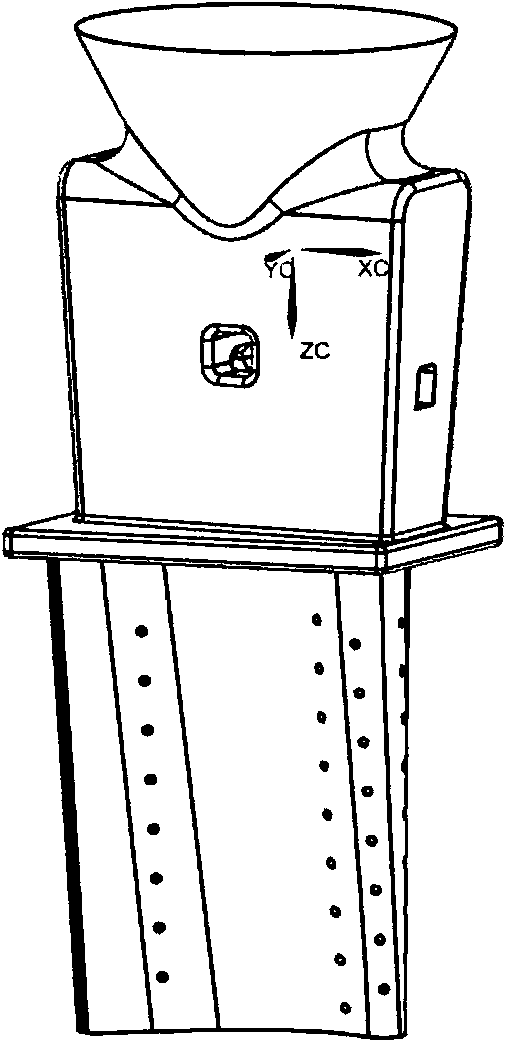
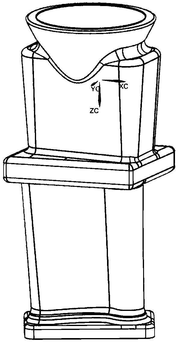
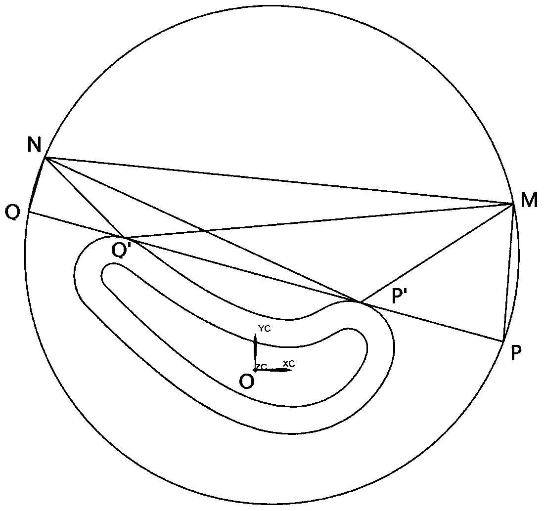
[0045] The present invention provides an example of determining the placement position of a turbine blade mold of a certain type of gas turbine in a directional solidification furnace. As shown in Figure 1(a) and (b), the casting mold and blade wireframe diagram of the turbine blade, figure 2 It is a transverse cross-sectional view of the blade end, which is a transverse cross-section selected by applying the method of the present invention, and we name it as cross-section 1. The origin of the coordinates shown in section 1 is the centroid of the section. The calculation program uses the MATLAB program given in Appendix A.

[0046] The geometric parameters of section 1 are as follows: P′(44.212395, 28.167773), Q′(-55.059670, 55.14212395); curve Arc P′Q′ The length of is 109.8536; the radius R of the great circle of the directional solidification furnace f is 800; the emissivity of the mold material in this example is 0.6, and the emissivity of the cooling device material is...


PUM


Abstract

The invention discloses a method for determining the laying position of a casting mold in a directional solidification casting. The method includes the steps: dividing the outer wall of a high-temperature alloy casting into a convex structure area and a concave structure area; determining the mass center connecting curve of the high-temperature alloy casting; selecting a plurality of transverse sections along a direction parallel to the growth direction of high-temperature alloy casting directional crystals; analyzing heat dissipation of the selected transverse sections to obtain the average radiative angle factor of a concave portion of each transverse section, adjusting the laying position of the casting mold in a directional solidification furnace, comparing the average radiative angle factors of the concave portions of the selected transverse sections at different positions in the directional solidification furnace, and determining the optimal laying position of the casting mold in the directional solidification furnace when the average radiative angle factor of the concave portion of each selected transverse section is maximum by the aid of the position of the casting mold. By analyzing heat dissipation of the outer wall of the high-temperature alloy casting, the laying position beneficial to growth of directional crystal structures is obtained.

Description

【Technical field】 [0001] The invention belongs to the field of directional solidification manufacturing, and in particular relates to a method for determining the placement position of molds in directional solidification casting. 【Background technique】 [0002] The directional solidification casting process can make the grains of directional superalloy castings align along the direction of heat flow loss, which can basically eliminate the transverse grain boundaries perpendicular to the stress axis, thereby greatly improving the performance of superalloy castings, such as turbine blades. Mechanical properties and thermal performance. However, in the actual production process, the produced oriented superalloy castings often contain crystal defects, such as local polycrystalline castings and crystal orientation deviations; The successful manufacture of castings cannot be guaranteed without changing the control conditions. [0003] In view of the two shortcomings of direction...

Claims


Application Information

Patent Timeline
IPC IPC(8): B22D27/00
Inventor 李涤尘廉媛媛鲁中良
Owner XI AN JIAOTONG UNIV
Learn More