A circular tube billet double ejector rod positioning device

A positioning device and a round tube billet technology, applied in the direction of tubular objects, gas flame welding equipment, applications, etc., can solve the problems of affecting operation efficiency, unfavorable tube billet cutting work, increasing maintenance costs, etc., to ensure equipment and personal safety, The effect of shortening alignment and positioning time and improving work efficiency

Active Publication Date: 2015-11-18
ANGANG STEEL CO LTD
View PDF5 Cites 0 Cited by
  • Summary
  • Abstract
  • Description
  • Claims
  • Application Information

AI Technical Summary

Problems solved by technology

Due to the long length and high mass of the round tube, the inertia of the running round tube is very large, and the double roller table transports two round tubes at the same time, so the impact force of the round tube on the baffle is relatively large, and the impact Afterwards, there is a rebound process, which not only often causes the positioning deviation of the round tube billet, the cut to length is not accurate, which is not conducive to the cutting work of the tube billet; moreover, the positioning time is long, which affects the operation efficiency
At the same time, it is very easy to damage or deform the baffle, which not only increases maintenance costs, but also poses certain safety hazards
Therefore, there is an urgent need to install a circular tube billet positioning device at the front and back of the double roller table to adapt to the cutting work and avoid potential safety hazards such as positioning deviation and equipment damage.

Method used


Image

  • A circular tube billet double ejector rod positioning device
  • A circular tube billet double ejector rod positioning device
  • A circular tube billet double ejector rod positioning device

Examples


Embodiment Construction

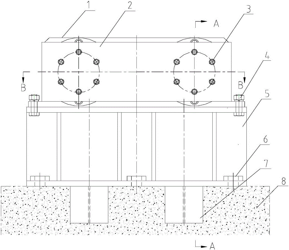
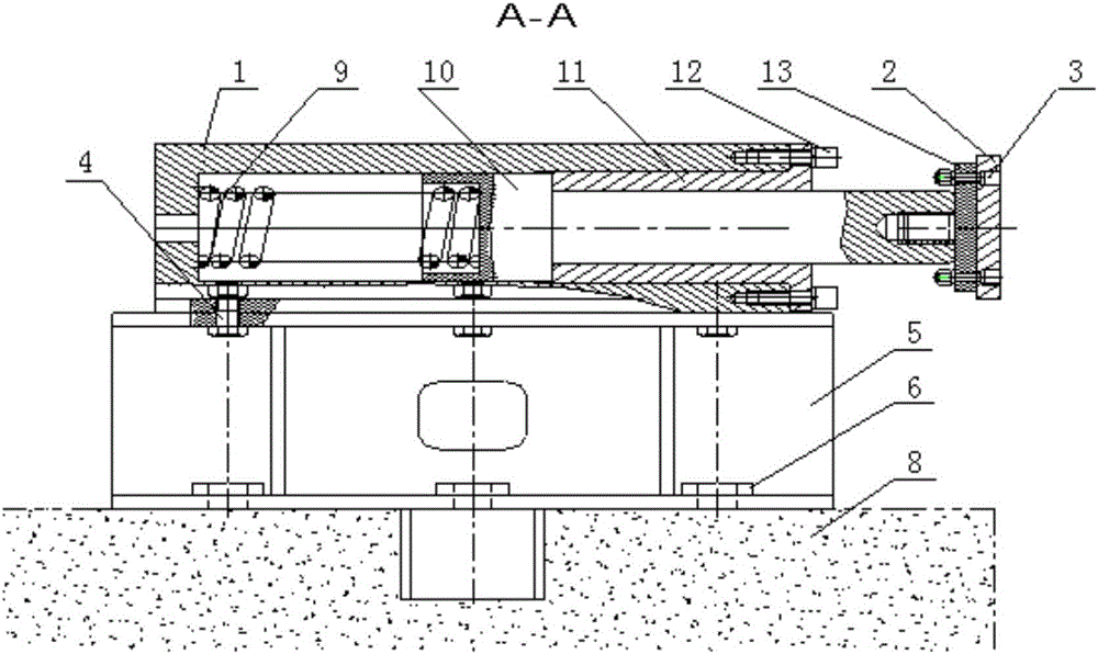
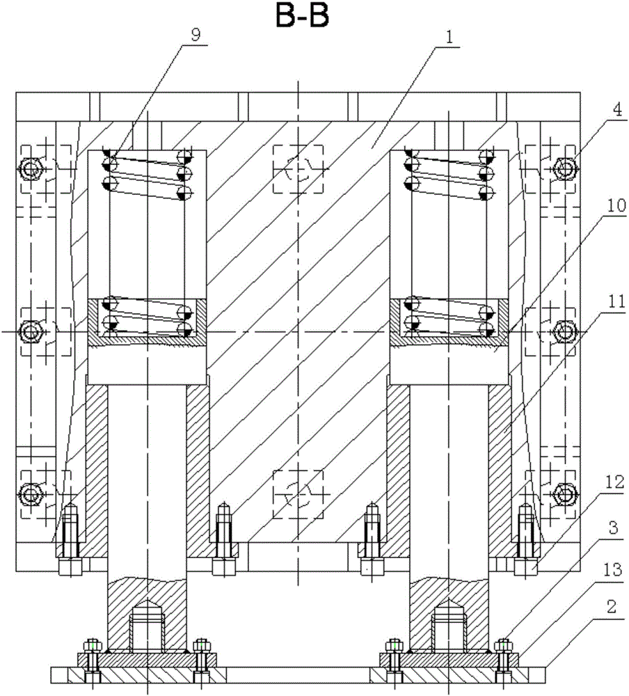
[0019] It can be seen from the accompanying drawings that the circular tube blank double ejector rod positioning device of the present invention is mainly composed of a buffer seat 1, a baffle plate 2, a connecting bolt 3, a fixing bolt 4, a base 5, an anchor bolt 6, a spring 9, a ejector rod 10, a Rod sleeve 11, locking bolt 12, bumper 13 are formed.

[0020] There are two push rods 10, which are "T" shaped rods made of two sections of cylinders with different diameters and lengths processed from round steel. There is a spring groove at the big end of the "T" shaped push rod 10, and a small end is provided with a spring groove. There is a connecting hole with an internal thread, so as to be connected with the bumper 13.

[0021] The push rod sleeve 11 is a "T" shaped sleeve with a push rod hole in the middle and a valgus edge at one end, and 12 bolt holes are arranged at equal intervals along the valgus edge circumference.

[0022] The buffer seat 1 has a convex shape as a w...


PUM


Abstract

The invention provides a double ejector rod type positioning device for circular pipe billets. The double ejector rod type positioning device comprises a base, buffer seats, springs, ejector rods, ejector rod sleeves, collision heads, a baffle plate and bolts; the large heads of the two T-shaped ejector rods are inward and are arranged in ejector rod holes of the buffer seats in a sliding mode respectively; the springs which are arranged at the bottoms of the ejector rod holes are pressed to abut against the bottom walls through spring grooves; the thin diameter portions of the two T-shaped ejector rods are arranged in the ejector rod sleeves in a sliding mode; the thin ends of the ejector rod sleeves abut against the large heads of the ejector rods; the outer turning edges of the thick ends of the ejector rod sleeves are fixed at the opened ends of the buffer seats through the locking bolts; the two protruding collision heads are connected into connecting holes of the small heads of the ejector rods through threads respectively; two bilateral sides of the rectangular baffle plate are fixed outside the two collision heads through the connecting bolts respectively; the buffer seats are fixed on the base through the fixing bolts. According to the double ejector rod type positioning device for the circular pipe billets, the impact force on the baffle plate of the circular pipe billets can be absorbed and eased and accordingly the two circular pipe billets can be aligned and positioned accurately in the double roller channel conveying process, the working efficiency is improved, the maintenance cost is reduced, and the device and personal safety is ensured.

Description

technical field [0001] The invention belongs to the field of steel rolling equipment, and in particular relates to a double-ejector positioning device used before and after flame cutting of a seamless pipe round billet. Background technique [0002] In the production of seamless steel pipes, it is necessary to cut long continuous casting round billets to length. The flame cutting machine is an important equipment in the material preparation process. Originally, before and after the four-bar torch of the flame cutting machine is used for flame cutting, there are baffles made of steel plates at both ends of the double roller table. Relying on the forward and reverse of the double roller table, the two round pipes to be cut and cut The billet is transported to the baffles set at both ends in forward and reverse directions, and the ends of the round tube billet are aligned and positioned for buffering by using the baffles. Due to the long length and high mass of the round tube...

Claims


Application Information

Patent Timeline
Patent Type & Authority Patents(China)
IPC IPC(8): B23K7/10
CPCB23K7/10B23K2101/06
Inventor 古红光孙野
Owner ANGANG STEEL CO LTD
Why Eureka
Try Eureka