Clamp used for processing thin-wall sleeve component

A technology of thin-walled sleeves and fixtures, which is applied to metal processing machinery parts, manufacturing tools, metal processing equipment, etc., can solve the requirements of difficult and reliable positioning of thin-walled sleeve parts and the inability to ensure the roundness of thin-walled sleeve parts, Affecting parts processing quality and other issues

Active Publication Date: 2014-04-23
ZOOMLION HEAVY IND CO LTD
View PDF5 Cites 5 Cited by
  • Summary
  • Abstract
  • Description
  • Claims
  • Application Information

AI Technical Summary

Problems solved by technology

[0002] In the field of mechanical processing, it is easy to affect the processing quality of parts due to the difficulty of reliable positioning of thin-walled sleeve parts
[0003] Especially in the prior art, conventional three-jaw chucks are often used to position thin-walled sleeve parts. Even if the processed parts meet the requirements in the clamped state, it is possible that after the chuck is removed, However, deformation occurs so that the parts are easily formed into parts corresponding to the shape of the three-jaw chuck, so that the roundness requirements of the thin-walled sleeve parts cannot be guaranteed.

Method used


Image

  • Clamp used for processing thin-wall sleeve component
  • Clamp used for processing thin-wall sleeve component

Examples


Embodiment approach

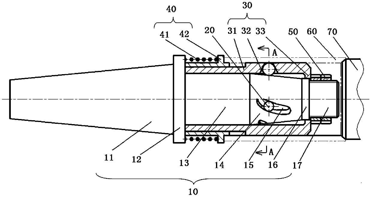
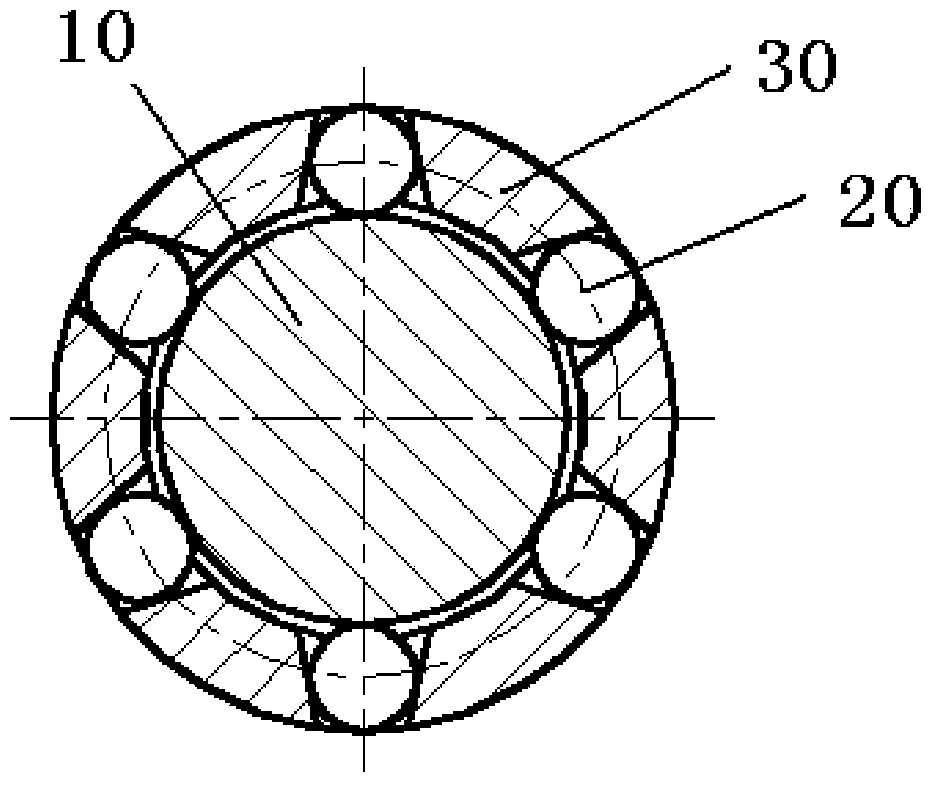
[0031] As another specific embodiment of the present invention, the clamp also includes a sleeve 30, the side wall of the sleeve 30 is provided with ball receiving holes 32 along the circumference of the sleeve 30, and each ball receiving hole 32 holds a One ball 20, and each ball 20 is in contact with the truncated portion 14, so that the ball 20 can protrude outward from the ball receiving hole 32 to form a fixed position for the thin-walled sleeve member 60 when being pressed to the mounting portion 11. Heart function. At this time, the sleeve 30 can be installed at the larger diameter of the frustum-shaped portion 14, that is to say, the sleeve 30 is sleeved on the frustum-shaped portion 14 and axially positioned using the larger diameter portion of the frustum-shaped portion 14. .

[0032] In addition, it is also possible to use figure 1 The shoulder portion 12 in the center is positioned axially. In this way, when the ball 20 is subjected to the cutting force transmit...


PUM


Abstract

The invention discloses a clamp used for processing a thin-wall sleeve component. The clamp comprises a main body portion (10). An installation portion (11) used for installing the clamp on a processing machine and a work-piece arrangement portion used for clamping the thin-wall sleeve component (60) are formed in the main body portion (10). The clamp is characterized in that the work-piece arrangement portion comprises a cone-shaped portion (14) which becomes smaller from the installation portion (11), and balls (20). The balls (20) can abut against the thin-wall sleeve component (60) and move along the axial direction of the cone-shaped portion (14) so as to protrude outwards and exert centring effect on the thin-wall sleeve component (60), and therefore the clamping force exerted on the thin-wall sleeve component (60) can be adjusted accurately, and the thin-wall sleeve component does not deform.

Description

technical field [0001] The present invention relates to a jig, in particular, to a jig for machining thin-walled sleeve parts. Background technique [0002] In the field of mechanical processing, the processing quality of the parts is easily affected due to the difficulty of reliable positioning of the thin-walled sleeve parts. [0003] Especially in the prior art, conventional three-jaw chucks are often used to position thin-walled sleeve parts. Even if the processed parts meet the requirements in the clamped state, it is possible that after the chuck is removed, However, deformation occurs so that the component is easily formed into a component corresponding to the shape of the three-jaw chuck, so that the roundness requirement of the thin-walled sleeve component cannot be guaranteed. Contents of the invention [0004] The technical problem to be solved by the present invention is to provide a jig for processing thin-walled sleeve parts, which will not deform the thin-w...

Claims


Application Information

Patent Timeline
Patent Type & Authority Applications(China)
IPC IPC(8): B23Q3/12
CPCB23Q3/12
Inventor 金灿
Owner ZOOMLION HEAVY IND CO LTD
Why Eureka
Try Eureka