Rail clamp and track running mechanism

A technology of traveling mechanism and rail clamping device, which is applied in the direction of traveling mechanism, brake components interacting with rails, railway car body parts, etc. It can solve the problems of unadjustable clamping force, narrow space, inconvenient inspection and maintenance, etc. , to achieve the effect of convenient inspection and maintenance, reasonable structure layout and high reliability

Active Publication Date: 2017-02-01
CHINA SHENHUA ENERGY CO LTD +1
View PDF7 Cites 0 Cited by
  • Summary
  • Abstract
  • Description
  • Claims
  • Application Information

AI Technical Summary

Problems solved by technology

Similar rail clamps generally have many problems. When the spring 7 enters the fatigue period after use, the clamping force cannot ensure that the rail clamp can clamp the track 52, so the track running mechanism is likely to be due to the rail clamp not being fully clamped. track and slide, and eventually lead to accidents; when clamping, it relies on spring force to clamp, and the clamping force cannot be adjusted, so that the clamping degree of the clamp 3 cannot be adjusted. In addition, this type of rail clamp is due to the use of Integrated layout, the hydraulic cylinder 8 is set inside the system, and the space is small so it is not convenient for inspection and maintenance
The traveling mechanism is arranged below the housing of the rail clamp, and the rail clamp is connected to the traveling mechanism through connecting bolts 9. Because the inertial force of the rail clamp is huge and the state of motion changes frequently, the connecting bolt 9 is frequently subjected to transverse shear force, so The connecting bolt 9 is very easy to break and cause an accident

Method used


Image

  • Rail clamp and track running mechanism
  • Rail clamp and track running mechanism
  • Rail clamp and track running mechanism

Examples


Embodiment Construction

[0043] Specific embodiments of the present invention will be described in detail below in conjunction with the accompanying drawings. It should be understood that the specific embodiments described here are only used to illustrate and explain the present invention, and are not intended to limit the present invention.

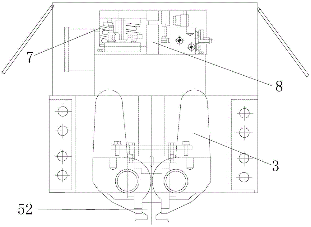
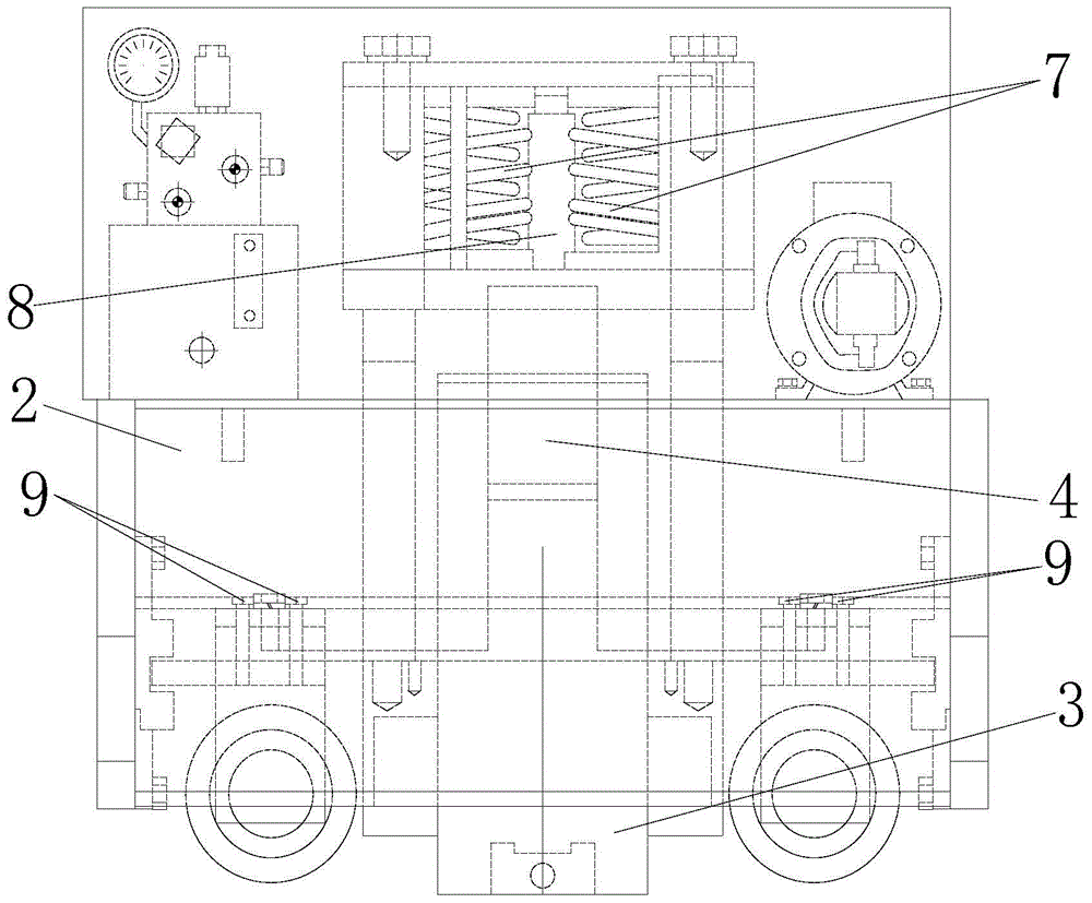
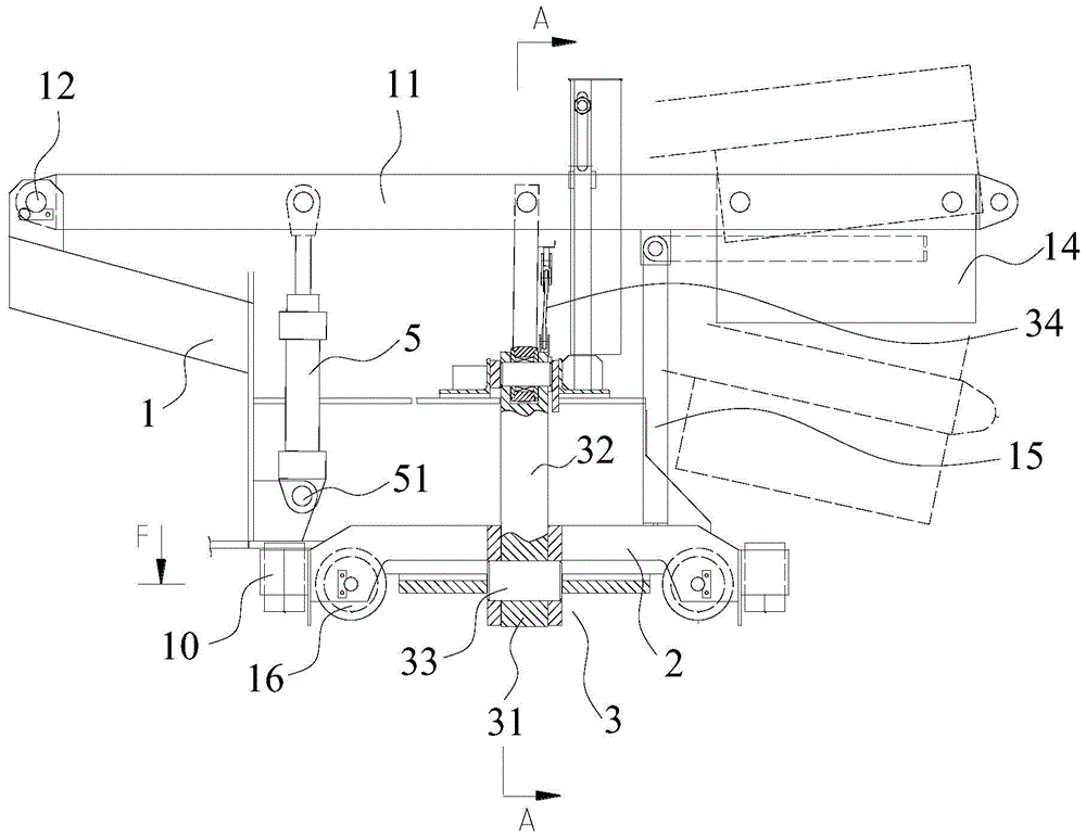
[0044] The invention provides a rail clamp, by figure 1 , figure 2 and image 3 From the comparison, it can be seen that the rail clamp of the present invention is structurally improved. Specifically, see Figure 4 , Figure 5 , Figure 6 and Figure 7 As shown, the rail clamp includes: a mounting bracket 1, the mounting bracket 1 is used to be installed on the track traveling mechanism and has a clamp installation groove; the traveling bracket 2, the traveling bracket 2 is equipped with a plurality of floating rail clamps that walk along the track Wheel 16; track clamp 3, the track clamp 3 is accommodated in the clamp mounting groove and includes two cl...


PUM


Abstract

The invention discloses a track clamping device. The track clamping device comprises an installing support (1), a walking support (2), a track clamp (3), a wedge (4) and a wedge lifting driving mechanism, wherein the track clamp (3) comprises a clamping part (31) and clamp handle parts (32), and the wedge lifting driving mechanism is connected with the installing support (1) and can drive the wedge (4) to insert between the two clamp handle parts (32), so that the clamping part (31) pivots around a rotating shaft (33) to clamp a track (52), or the wedge (4) is lifted upwards away from the portion between the two clamp handle parts (32), so that the clamping part (31) loosens the track (52). In addition, the invention further discloses a track walking mechanism comprising the track clamping device. The track clamping device can provide clamping force higher in reliability.

Description

technical field [0001] The invention relates to the field of rail clamps, in particular to a rail clamp. In addition, the present invention also relates to a rail traveling mechanism comprising the rail clamp. Background technique [0002] The rail clamp is a windproof and anti-skid device installed on the rail carrier for outdoor work (such as loading and unloading bridges, gantry cranes, bucket wheel stackers and reclaimers, gantry cranes, etc.). [0003] Such as figure 1 and figure 2 The existing rail clamp generally includes a bracket 2, a rail clamp 3, a spring 7 and a hydraulic cylinder 8. The rail clamp makes the wedge 4 move downward through the elongation of the spring, and then the handle of the rail clamp 3 is stretched. Open, the clamping part is clamped, and finally the clamping action of the rail is realized; at the same time, the rail clamp forces the spring to overcome its own elastic force to contract through the contraction of the hydraulic cylinder, an...

Claims


Application Information

Patent Timeline
Patent Type & Authority Patents(China)
IPC IPC(8): B61H7/12B66C9/18
Inventor 韩斌鲍建员刘华琳李建光宋文亮王敏刚马光辉肖雄建陈新峰赵炎
Owner CHINA SHENHUA ENERGY CO LTD
Why Eureka
Try Eureka