Manual chamfering device of magnetic ring

A technology of chamfering device and magnetic ring, which is applied in the manufacture of inductors/transformers/magnets, grinding machines, electrical components, etc. It can solve the problems of low production efficiency, missing chamfers, uneven chamfering, etc., and achieve high production efficiency and no The effect of omission and uniform chamfering

Inactive Publication Date: 2014-04-23
WUJIANG ZHENYU SEWING EQUIP
View PDF8 Cites 1 Cited by
  • Summary
  • Abstract
  • Description
  • Claims
  • Application Information

AI Technical Summary

Problems solved by technology

This kind of artificial chamfering is not only labor-intensive and low in production efficiency, but also, the chamfering is uneven, and pits or missing chamfers are prone to occur.

Method used


Image

  • Manual chamfering device of magnetic ring

Examples


Embodiment Construction

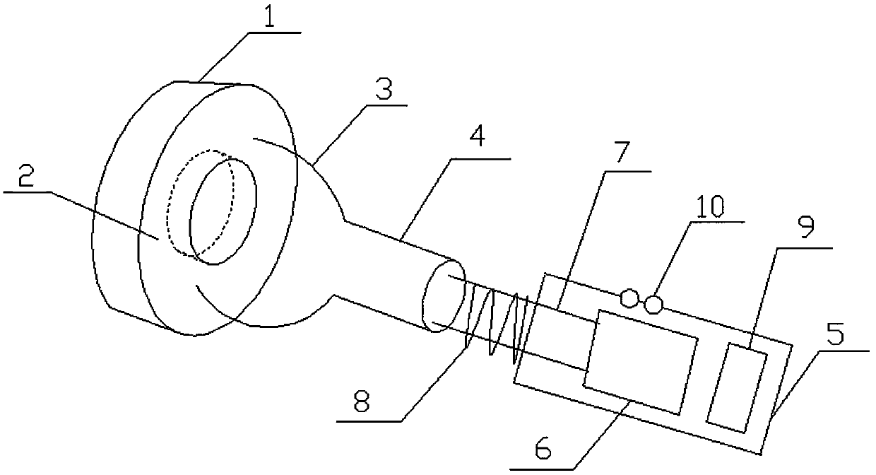
[0012] The present invention will be further described in detail below in conjunction with the accompanying drawings and specific preferred embodiments.

[0013] Such as figure 1 As shown, a magnetic ring manual chamfering device includes a ring 1 with a groove 2 in the middle and a handle 5 with a built-in motor 6. The groove 2 matches the end face of the magnetic ring to be chamfered. The bottom of the groove 2 is provided with a chamfering mechanism, the bottom of the ring 1 away from the groove 2 is fixed with a hollow threaded rod 4 with external threads through a connector 3, and the motor 6 is connected with a The rotating shaft 7, the extending end of the rotating shaft 7 is provided with an external thread 8 matching the hollow threaded rod 4, and the handle 5 is also provided with a switch button 10. The rotating shaft 7 is threadedly connected with the hollow threaded rod 4 and is detachable, and the corresponding ring 1 can be replaced according to the differe...


PUM


Abstract

The invention discloses a manual chamfering device of a magnetic ring. The manual chamfering device of the magnetic ring comprises a ring provided with a groove in the middle, and a handle internally provided with a motor. The groove is matched with the annular end face of the magnetic ring to be chamfered, and a chamfer polishing mechanism is arranged at the bottom of the groove. The bottom, away from the side of the groove, of the ring is fixedly provided with a hollow threaded rod provided with outer threads through a connecting piece. The motor is connected with a rotation shaft extending out of the top end of the handle, and the extending end of the rotation shaft is provided with outer threads matched with the hollow threaded rod. The handle is provided with a switch key. By means of the structure, the ring end face of the magnetic ring to be chamfered is arranged in the groove of the ring, the rotation shaft drives the ring to rotate under the drive of the motor, when the chamfer polishing mechanism in the groove rotates, an inner corner and an outer corner of the magnetic ring to be chamfered are chamfered, and therefore chamfering is even and free of leakage, and production efficiency is high.

Description

technical field [0001] The invention relates to a magnetic ring production auxiliary processing device, in particular to a magnetic ring manual chamfering device. Background technique [0002] In the production of existing magnetic rings, especially ferrite magnetic rings, in the molding and pressing stage, even if the process corners are designed, sharp chamfers still inevitably appear. Because the sharp part may scratch the insulation layer of the coil during the subsequent coil winding, resulting in safety accidents; it may also cause poor painting of the corners during the spraying process, resulting in poor voltage resistance. After the pressing is completed, it will be required to chamfer the corners of the magnetic ring. However, the chamfering method of the existing large magnetic ring is mainly manual chamfering, and the manual chamfering mainly uses a knife or blade to rotate and scrape the corners of the magnetic ring. This kind of artificial chamfering not only...

Claims


Application Information

Patent Timeline
Patent Type & Authority Applications(China)
IPC IPC(8): B24B9/06H01F41/02
CPCB24B9/06H01F41/0286
Inventor 胡粉义
Owner WUJIANG ZHENYU SEWING EQUIP
Why Eureka
Try Eureka