Automatically-adjustable dome for truck
A technology of automatic adjustment and shroud, applied in the direction of car body, vehicle parts, streamlined body, etc., can solve the problem of inconvenient adjustment of shroud, and achieve the effect of simple structure, fuel saving and light weight
- Summary
- Abstract
- Description
- Claims
- Application Information
AI Technical Summary
Problems solved by technology
Method used
Image
Examples
Embodiment Construction
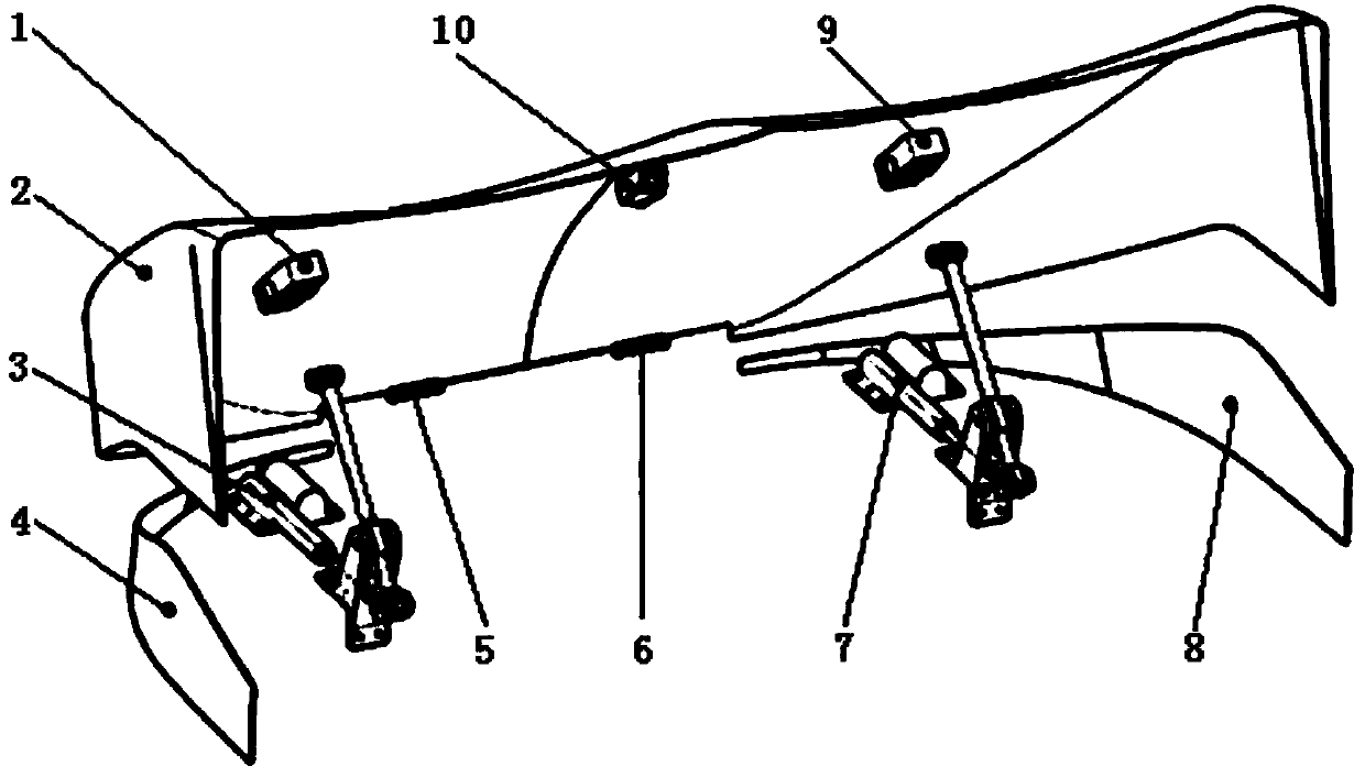
[0027] in accordance with figure 1 , The overall structure of the shroud is center-symmetrical, divided into left part I and right part II. Only the left part I is illustrated here, and the right part II is exactly the same as the left part I. The fairing body includes the upper part 2 of the fairing and the lower part I4 of the fairing. The upper part 2 of the shroud is fixed on the front end of the top of the cab through hinges; the lower part I4 of the shroud is symmetrically fixed and fixed on the left and right ends of the top of the cab through positioning holes.
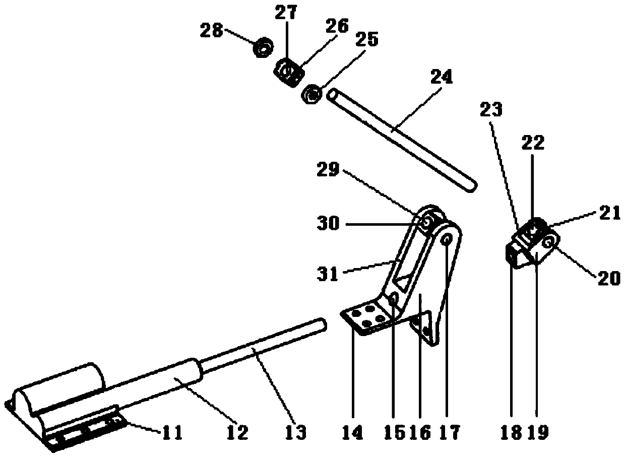
[0028] in accordance with figure 1 and figure 2, Push rod support structure Ⅰ3 includes electric push rod Ⅰ12, support Ⅰ16, hinged joint Ⅰ19, rotating block Ⅱ21, rotating block Ⅰ30, double-ended threaded connecting rod Ⅰ24, rolling joint Ⅰ26, rolling bearing Ⅰ25 and rolling bearing Ⅱ28. The electric push rod I12 and the support I16 are fixed on the left side of the top of the cab through the positioning...
PUM
 Abstract
Description
Claims
Application Information
 - R&D
- Intellectual Property
- Life Sciences
- Materials
- Tech Scout
- Unparalleled Data Quality
- Higher Quality Content
- 60% Fewer Hallucinations
Browse by: Latest US Patents, China's latest patents, Technical Efficacy Thesaurus, Application Domain, Technology Topic, Popular Technical Reports.
© 2025 PatSnap. All rights reserved.Legal|Privacy policy|Modern Slavery Act Transparency Statement|Sitemap|About US| Contact US: help@patsnap.com


