Guide rod of submersible water impeller

A technology of submersible flow propeller and guide rod, applied in the field of frame, sliding sleeve, and submersible flow propeller guide rod, can solve the problems of large economic loss and long production shutdown, reduce labor intensity, increase contact area and The effect of bearing area and prolonging service life

Inactive Publication Date: 2014-04-23
JIANGMEN XINHUI DISTRICT LONGQUAN SEWAGE TREATMENT CO LTD
View PDF3 Cites 8 Cited by
  • Summary
  • Abstract
  • Description
  • Claims
  • Application Information

AI Technical Summary

Problems solved by technology

For the maintenance and replacement of the guide rod 2 and the bracket 5, the pool must be emptied and operated at the bottom of the pool. The processing process requires a long time of shutdown, resulting in large economic losses

Method used


Image

  • Guide rod of submersible water impeller
  • Guide rod of submersible water impeller
  • Guide rod of submersible water impeller

Examples


Embodiment Construction

[0028] The guide rod of the submersible flow propeller of the present invention will be further described below in conjunction with the accompanying drawings.

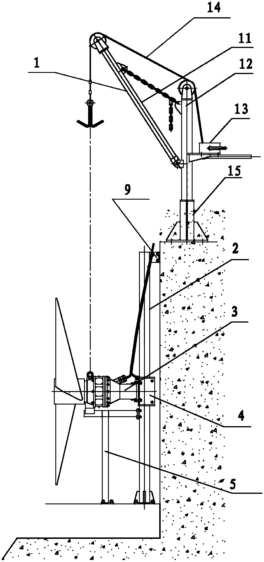
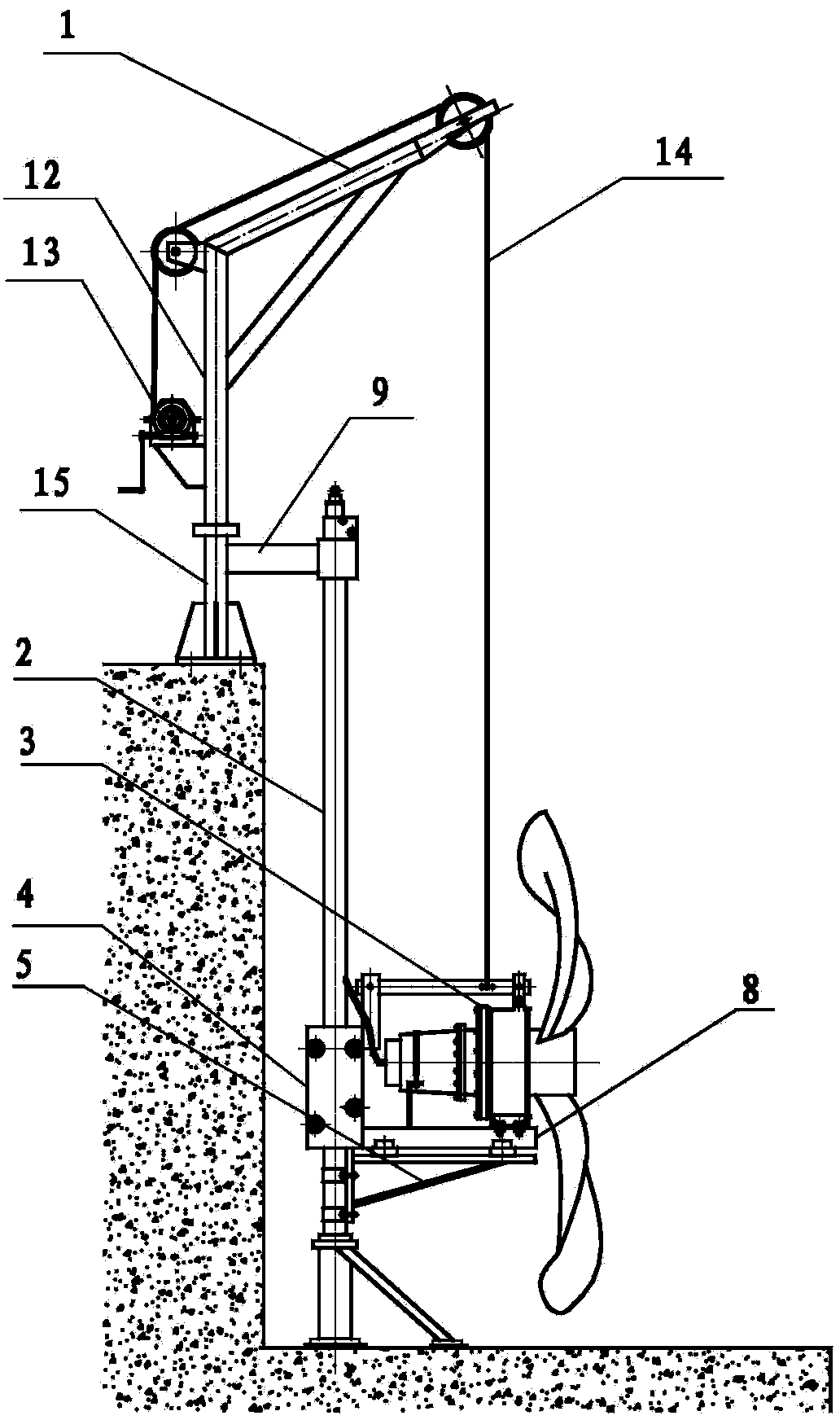
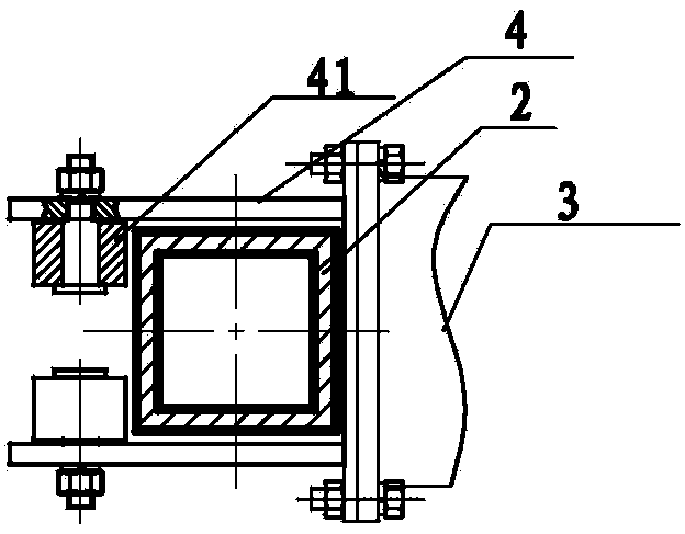
[0029] see Figure 4 , Figure 5 , apply the submersible flow propeller guide rod of the present invention on the hoist of the prior art, its U-shaped fixing frame 6 is arranged on the top of the pool, and the double-track cylindrical guide rod 2 is two parallel to each other and perpendicular to the bottom surface of the pool at the same time. Cylindrical structure. The upper end of the cylindrical guide rod 2 is fixedly installed on the U-shaped fixing frame 6, and the lower end is movably inserted into the V-shaped fixing column 7 at the bottom of the pool; The support 76 is reinforced to obtain a more solid, reliable, and durable use effect; there are two semi-cylindrical sliding sleeves 4, which are symmetrically installed on both sides of the base 54 of the tripod bracket 5; the tripod bracket 5. The semi-cyli...


PUM


Abstract

The invention discloses a guide rod of a submersible water impeller. The guide rod comprises a lifting frame (1), guide rods (2), a main machine (3), two sliding sleeves (4) and a bracket (5), wherein a fixing frame (6) is installed at the top of a tank; the guide rods (2) are of two parallel cylindrical structures installed vertically; T-shaped joints (22) arranged at the upper ends of the cylindrical structures are fixedly installed in the fixing frame (6), and V-shaped guide heads (23) arranged at the lower ends of the cylindrical structures are movably inserted into fixing columns (7) at the bottom of the tank; the two sliding sleeves (4) are symmetrically installed on the two sides of a base (54) at the upper part of the bracket (5); the bracket (5) is movably sleeved between the two guide rods via the sliding sleeves (4); the main machine (3) is fixedly installed on the bracket (5) to form an integral structure with the bracket (5) and the sliding sleeves (4). According to the guide rod of the submersible water impeller, the main machine, the bracket and the sliding sleeves can be lifted out of the water surface to undergo inspection, maintenance and wear repair and can be lifted or installed at the top of the tank.

Description

technical field [0001] The invention relates to sewage treatment engineering machinery, in particular to the guide rods, sliding sleeves and racks of submersible flow propellers used in anaerobic tanks, anoxic tanks, aerobic tanks, aeration tanks and the like in sewage treatment projects. Background technique [0002] In the current sewage treatment industry, the installation structure mode of the submersible flow propeller can be roughly summarized into five parts: lifting frame 1, guide rod 2 (or square column, the same below), main engine 3, sliding sleeve 4, bracket 5. [0003] in, figure 1 The shown hoisting frame 1 is composed of a movable jib 11, a bracket 12, a hoisting device 13, a hoisting wire rope 14, a support column 15, and the like. figure 2 The shown hoisting frame 1 is composed of a bracket 12, a hoisting device 13, a hoisting wire rope 14, a support column 15, and the like. In the current sewage treatment project, there are usually two installation meth...

Claims


Application Information

Patent Timeline
Patent Type & Authority Applications(China)
IPC IPC(8): C02F3/02B66C1/22
CPCY02W10/10
Inventor 游卫强陈光兴陈浩耿峰
Owner JIANGMEN XINHUI DISTRICT LONGQUAN SEWAGE TREATMENT CO LTD
Why Eureka
Try Eureka