
Radar level meter system and control method thereof

A technology of radar level meter and control method, which is applied in the direction of electrical program control, program control in sequence/logic controller, liquid/fluid solid measurement, etc., and can solve the problem that power consumption cannot meet the requirements, etc.

Inactive Publication Date: 2014-04-23
SHANGHAI XIONGFENG AUTO CONTROL ENGINEERING CO LTD
View PDF6 Cites 10 Cited by
  • Summary
  • Abstract
  • Description
  • Claims
  • Application Information

AI Technical Summary

Problems solved by technology

Industrial instruments mostly use two-wire 4-20MA, which requires less than 90mW for the entire system power consumption, so the peripheral circuits of the instrument plus the power consumption of the operating system cannot meet the requirements

Method used


Image

  • Radar level meter system and control method thereof
  • Radar level meter system and control method thereof
  • Radar level meter system and control method thereof

Examples


Embodiment

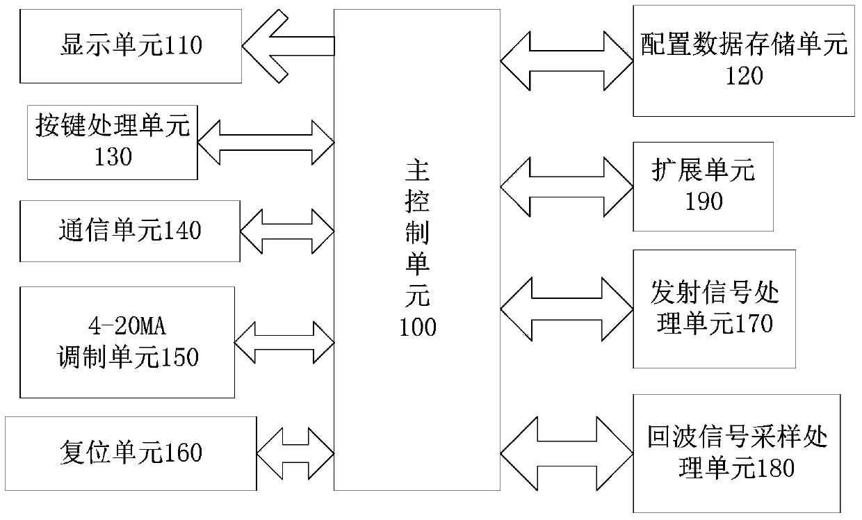
[0035] Such as figure 1 As shown, the radar level gauge system of the present invention includes a main control unit 100 and a display unit 110 connected to the main control unit 100, a configuration data storage unit 120, a key processing unit 130, and a communication unit 140,4 - 20MA modulation unit 150 , reset unit 160 , transmit signal processing unit 170 , echo signal sampling processing unit 180 and extension unit 190 .

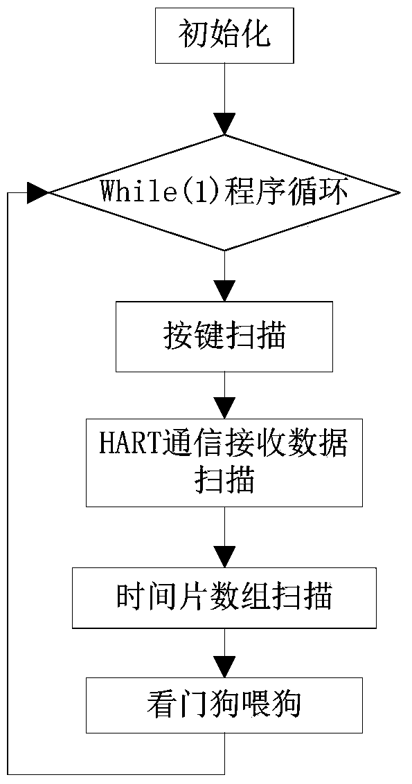
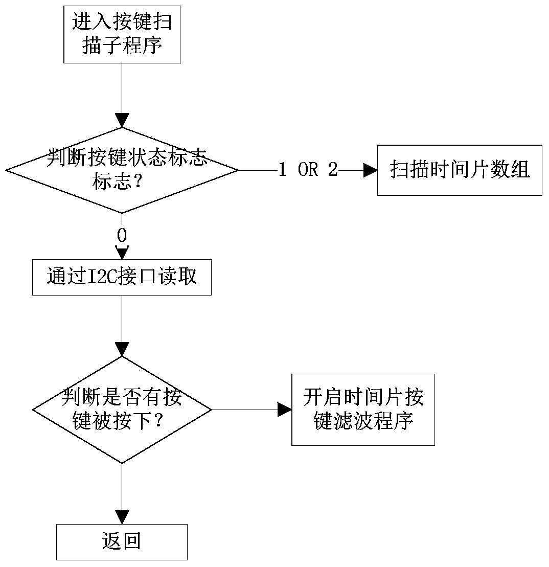
[0036] Such as figure 2 , image 3 and Figure 4 Shown, the control method of radar level gauge system of the present invention, it comprises the steps:

[0037] (1) The main control unit 100 starts the reference clock timer, allocates the start time of each unit according to its functional characteristics, and divides the units with long running cycle and low real-time performance into several sub-units, the main control unit The unit with strong real-time performance is executed once a week in the program cycle, and the unit with low real-time p...


PUM


Abstract

The invention aims to disclose a radar level meter system and a control method thereof. The radar level meter system comprises a master control unit, a display unit, a configuration data storage unit, a key processing unit, a communication unit, a 4-20MA modulation unit, a reset unit, a transmitted signal processing unit, an echo signal sampling and processing unit and an extension unit; the latter units are all connected with the master control unit. Compared to the prior art, the radar level meter system has the advantages that based on the control method, longer time is provided for the processing of the mathematical operation part in complex echo data, system reliability and timeliness can be met, accurate measurement is achieved, real-time response speed is high, measurement and outputting precision is high, and the aim of the invention is achieved.

Description

technical field [0001] The invention relates to a level gauge system and a control method thereof, in particular to a radar level gauge system and a control method suitable for the field of industrial automation. Background technique [0002] The radar level gauge measures the height of the liquid level by measuring the time delay of transmitting and receiving UWB (Ultra Wideband, also known as ultra-wideband radar wave) pulses. Material level value H=L-C*T / 2, where L is the length of the material container, C is the speed of light 3×10 8 m / s, T is the delay time of sending and receiving pulses. The radar level gauge is mostly used to measure the height of the material level between 0-70M, so the delay time of sending and receiving pulses is NS level. If it is directly processed, it is feasible to use a dedicated high-end DSP (digital signal processing) microprocessor, and the price is expensive. consumes more. Industrial instruments mostly use medium and low MCU controll...

Claims


Application Information

Patent Timeline
IPC IPC(8): G01F23/284G05B19/04
Inventor 张志国
Owner SHANGHAI XIONGFENG AUTO CONTROL ENGINEERING CO LTD
Learn More