Differential spectral imaging method

An imaging method, differential spectrum technology, applied in the field of spectral imaging, to achieve the effects of reducing spectral inhomogeneity, simplifying drive control, and reducing costs

Inactive Publication Date: 2014-04-23
INST OF FLUID PHYSICS CHINA ACAD OF ENG PHYSICS
View PDF10 Cites 6 Cited by
  • Summary
  • Abstract
  • Description
  • Claims
  • Application Information

AI Technical Summary

Problems solved by technology

At present, there is no technical method to break through the limitation of the spectral resol

Method used


Image

  • Differential spectral imaging method
  • Differential spectral imaging method
  • Differential spectral imaging method

Examples


Embodiment

[0066] The specific steps for realizing the method of the present invention will be described below with a specific example.

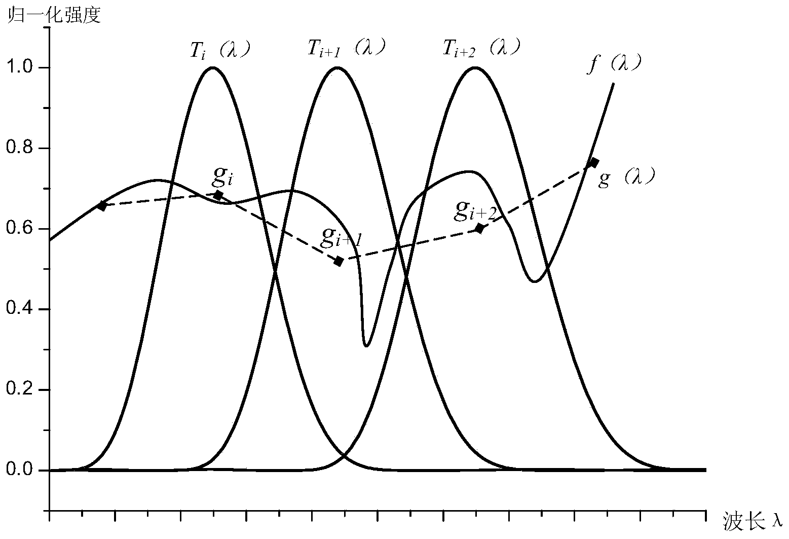
[0067] A liquid crystal phase retarder with a thickness of 5 μm and Δn of 0.2 is used, 31 pieces are cascaded in five stages, and combined with 6 polarizers according to the Loyt type to form a tunable liquid crystal filter. The height and width H are about 20nm; set the spectral function to be measured as f(λ), scan with a step size of 20nm, and measure the spectral intensity value of the discrete point. This value is the convolution of the filter function and the spectral function within the half maximum width, that is, 20nm An approximation of the sum of all spectral intensities in the range, indicating that the spectral resolving power of the tunable liquid crystal filter is 20nm.

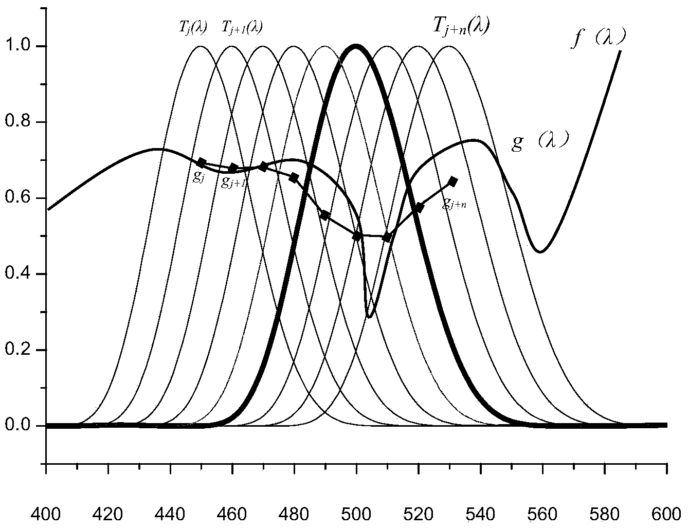
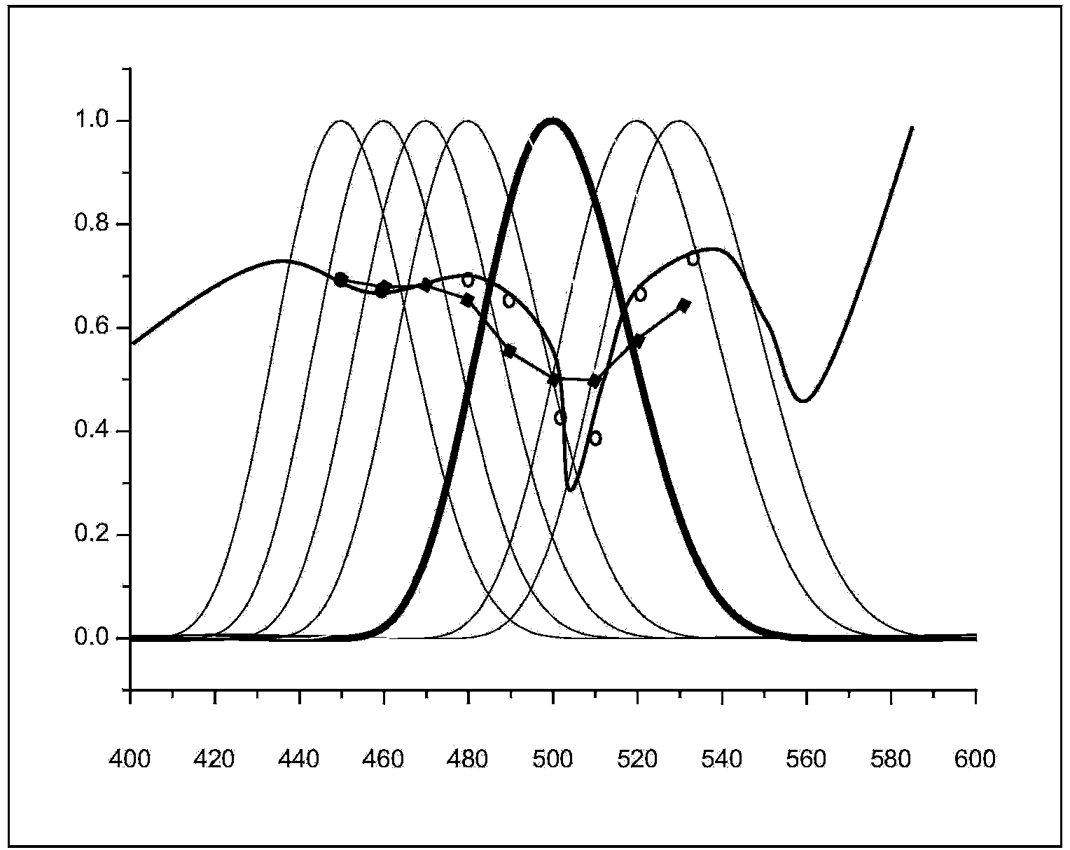
[0068] In order to achieve higher spectral resolving power, scan imaging is performed with a step size smaller than the half maximum width. For example, if a tunable l...


PUM


Abstract

The invention provides a differential spectral imaging method. The method is characterized by comprising the steps of dividing a tunable filter penetration peak into multiple sections on the basis of obtaining a tunable filter penetration rate function, namely differentiating a spectrum within a bandwidth, obtaining an integral equation containing multiple unknown numbers at every scanning time at the spectral imaging by adopting each section of spectrum as an unknown number, scanning and imaging for multiple times by adopting a step length which is smaller than the bandwidth so as to obtain an integral equation group; subducting surplus unknown spectrums in the equation group by utilizing a cut-off filter plate, so that the unknown numbers of the equation group is as many as equations, solving the linear equation group through integral transformation and error compensation, and obtaining a more precise spectrum structure of the tunable filter plate within the bandwidth interval. The spectral resolution capacity at the differential spectral imaging can be controlled by classifying the bandwidth of the filter, so that the narrow-band filter can be realized by utilizing the width filter, and the spectral resolution capacity and application range of a spectral imaging instrument can be greatly increased.

Description

technical field [0001] The present invention relates to spectral imaging technology. Background technique [0002] Spectral imaging technology has a wide range of application requirements in various fields. From the black-and-white photography technology of single-band amplitude imaging to color imaging, that is, the material spectrum is divided into red, green and blue in the visible light range. Even such a simple division greatly improves our identification of objects. ability. The use of optical filtering technology can divide the material spectrum into 100 segments, which will greatly improve our ability to identify fine spectral features of targets. It has great application value in the diagnosis of the health status of the surface of the inner wall of the organ and the monitoring of the physiological process of the living tissue. For example, the U.S. Airborne Visible / Near-Infrared Spectral Imager (AVIRIS) conducts efficient military reconnaissance with the support...

Claims


Application Information

Patent Timeline
IPC IPC(8): G01J3/28
Inventor 黄立贤张大勇刘仓理骆永全沈志学吴军罗飞王海峰
Owner INST OF FLUID PHYSICS CHINA ACAD OF ENG PHYSICS
Why Eureka
Try Eureka