Optical fiber detector for measuring salinity and measurement device using optical fiber detector

A fiber optic probe and measuring device technology, applied in measuring devices, material analysis through optical means, instruments, etc., can solve the problems of affecting the accuracy of measurement results, reducing the mechanical properties of optical fibers, and complicating the operation process, so as to achieve convenient composition, Easy-to-handle, inexpensive effects

Inactive Publication Date: 2014-04-23
NINGBO UNIV
View PDF5 Cites 11 Cited by
  • Summary
  • Abstract
  • Description
  • Claims
  • Application Information

AI Technical Summary

Problems solved by technology

This device using fiber Bragg gratings to measure salinity, although the sensing structure is simple, can achieve long-distance, distributed measurement, but the mechanical properties of the optical fiber after decay are greatly reduced, which will affect the accuracy of the measurement results during measurement In addition, hydrofluoric acid is a chemical that is harmful to humans and the natural environment, which inevitably increases the safety requirements for operations and complicates the operation process, which not only reduces production efficiency, but also increases increased production costs
[0004] In addition, commonly used salinity measuring instruments generally directly detect the water body to be measured, which cannot avoid the influence of sediment, dust, planktonic microorganisms, etc. in the water body, resulting in the detected salinity data being different from the actual sea water or the salt in other water bodies. Therefore, how to effectively eliminate the influence of other environmental factors in the water body is very important.

Method used


Image

  • Optical fiber detector for measuring salinity and measurement device using optical fiber detector
  • Optical fiber detector for measuring salinity and measurement device using optical fiber detector
  • Optical fiber detector for measuring salinity and measurement device using optical fiber detector

Examples


Embodiment Construction

[0025] The present invention will be further described in detail below in conjunction with the accompanying drawings and embodiments.

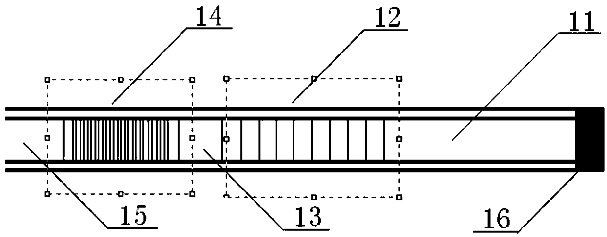
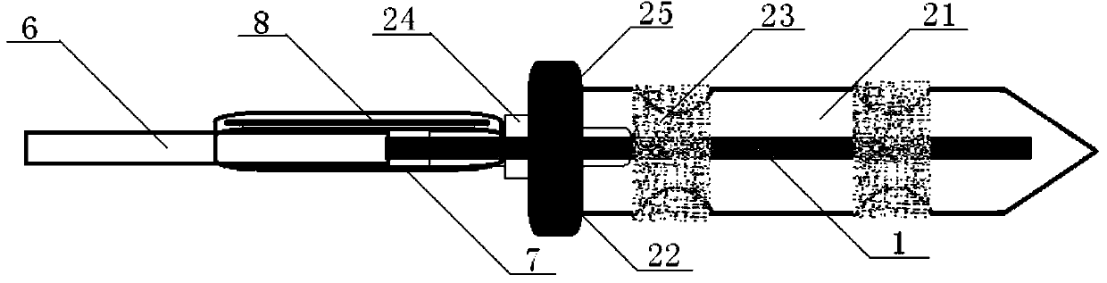
[0026] Such as figure 1 and image 3As shown, a fiber optic probe for salinity measurement includes a fiber optic probe 1 and a packaging sleeve that can enter the water body and filter out aquatic organisms and other solid particle impurities in the water body. The fiber optic probe 1 consists of a first An optical fiber 11, a long-period fiber grating 12, a second optical fiber 13, a fiber Bragg grating 14 and a third optical fiber 15, one end of the first optical fiber 11 is coated with a metal reflective film to form a metal-coated reflective film end 16, the first optical fiber 11 The other end of the fiber, the optical fiber carrying the long-period fiber grating 12, the second optical fiber 13, the optical fiber carrying the fiber Bragg grating 14, and the third optical fiber 15 are sequentially connected. The overall length of the fi...


PUM

PropertyMeasurementUnit
lengthaaaaaaaaaa
lengthaaaaaaaaaa
pore sizeaaaaaaaaaa

Abstract

The invention discloses an optical fiber detector for measuring the salinity and a measurement device using the optical fiber detector. The optical fiber detector is characterized by comprising an optical fiber probe, wherein the optical fiber probe is composed of a first optical fiber, a long-period optical fiber grating, a second optical fiber, fiber bragg gratings and a third optical fiber; one end of the first optical fiber is plated with a metal reflection membrane; the other end of the first optical fiber, an optical fiber carried with the long-period optical fiber grating, the second optical fiber, the optical fiber carried with the fiber bragg grating and the third optical fiber are connected with one another in sequence. The optical fiber detector for measuring the salinity has the advantages that the optical fiber detector is simple in whole structure and convenient to manufacture; the price of each part of the optical fiber is low and the ranges of the applicable environment temperature and environment depth are wide; the optical fiber detector is suitable for large-scale production; the measuring device using the optical fiber detector is convenient to assemble and is easy to operate by users; the measurement device can be used for accurately obtaining the salinity, the temperature and the depth of a water body in a large range in real time.

Description

technical field [0001] The invention relates to a salinity measurement technology, in particular to an optical fiber probe for salinity measurement and a measuring device using the optical fiber probe. Background technique [0002] Salt in water and food is an important parameter to measure the composition index, and a variety of related technical measurement methods have emerged in recent years. Commonly used technical means include conductivity to measure salinity, refractive index to measure salinity, etc. Correspondingly, there are also portable conductivity / salinity / temperature measuring instruments and portable refractive index / salinity / temperature measuring instruments. At present, the measurement object of this type of portable salinity measuring instrument is single. In the process of testing the salinity of the water body, it is often impossible to measure the water temperature and water depth at the same time, and it is necessary to add other measuring instruments...

Claims


Application Information

Patent Timeline
Patent Type & Authority Applications(China)
IPC IPC(8): G01N21/01G01N21/17
Inventor 张斌陶卫东何如双沈祥董建峰潘雪丰段天臣
Owner NINGBO UNIV
Why Eureka
Try Eureka