Cooperative clustering transmission method

A transmission method and a technology of cooperative clusters, applied in transmission systems, digital transmission systems, multiple use of transmission paths, etc., can solve problems such as large overhead and complexity

Inactive Publication Date: 2014-04-23
UNIV OF SCI & TECH BEIJING
View PDF5 Cites 14 Cited by
  • Summary
  • Abstract
  • Description
  • Claims
  • Application Information

AI Technical Summary

Problems solved by technology

In the dynamic clustering scheme, by updating and exchanging channel state information in real time, each user terminal can always select its best transmission base station to form a cooperative cluster for transmission, so that a better performance gain can be obtained, but Also at the cost of greater overhead and complexity

Method used


Image

  • Cooperative clustering transmission method
  • Cooperative clustering transmission method
  • Cooperative clustering transmission method

Examples


Embodiment

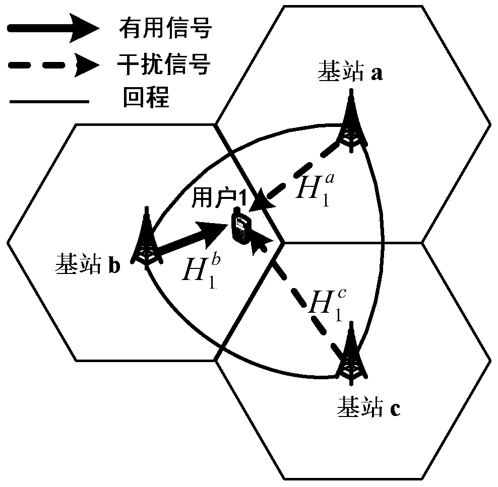
[0036] Assume that the entire cellular system includes N base stations, each base station has Nt transmit antennas, and each user terminal has N r Root receiving antenna. In downlink transmission, B (Bfigure 1 It is a schematic diagram of a typical downlink CoMP joint transmission system model. Such as figure 1 As shown, three base stations cooperate to serve users at the same time, and channel state information and transmitted data are shared among the three cooperative base stations through a backhaul link.

[0037] Suppose user k is at the edge of the cell where base station b is located (that is, the cell is the serving cell of user k), and the cooperative cluster where base station b is located is C k . Then the signal strength received by user k from base station b is:

[0038] y k b = H k b w k b x...


PUM


Abstract

The invention discloses a cooperative clustering transmission method which comprises the following steps: users are firstly divided into cell-center users and edge users according to channel isolation; then, the edge users are further divided into intra-cluster cell-edge users and cluster edge users according to received signal power of each user; and finally, non-cooperative, static cluster cooperative and dynamic cluster cooperative schemes are respectively adopted for the three different types of users so as to reduce interference from intra-cluster other cell sites as well as interference from inter-cluster other sites. According to the invention, different cooperative transmission modes are adopted according to different types of users, and good throughput gain can be obtained by low complexity and return cost.

Description

technical field [0001] The invention belongs to the technical field of coordinated multi-point transmission, and more specifically, relates to a cooperative clustering transmission method. Background technique [0002] CoMP (Coordinated Multiple Points, coordinated multi-point transmission) technology is one of the key technologies of LTE-A (LTE-Advanced, evolution of LTE) formulated by 3GPP (The 3rd Generation Partnership Project, third generation partnership project). In the LTE-A system, by adopting Orthogonal Frequency Division Multiplexing (OFDM) technology, the interference in the cell can be effectively eliminated. However, inter-cell interference has always been an urgent problem to be solved. In practical applications, frequency resources are becoming more and more scarce, and the requirements for spectrum efficiency are also higher. Therefore, it is hoped that the frequency reuse factor of the system is 1, but in this way, users at the edge of the cell will suffer...

Claims


Application Information

Patent Timeline
Patent Type & Authority Applications(China)
IPC IPC(8): H04W72/08H04B7/02H04L5/00
Inventor 刘健石海丽隆克平
Owner UNIV OF SCI & TECH BEIJING
Why Eureka
Try Eureka