Heat-insulation flowerpot

A flowerpot and heat preservation lamp technology, applied in the field of horticulture, can solve the problems of plants that are not cold-resistant and cannot survive in the cold environment in the north, and achieve the effect of solving the problem of being unable to survive in the cold environment in the north and preventing the plants from being frozen to death.

Active Publication Date: 2014-04-30
QIDONG QINGQING VEGETABLE & FRUIT RURAL LAND STOCK PROFESSIONAL COOP
View PDF10 Cites 4 Cited by
  • Summary
  • Abstract
  • Description
  • Claims
  • Application Information

AI Technical Summary

Problems solved by technology

Solved the problem that plants that are not cold-resistant...

Method used


Image

  • Heat-insulation flowerpot
  • Heat-insulation flowerpot
  • Heat-insulation flowerpot

Examples


Embodiment 1

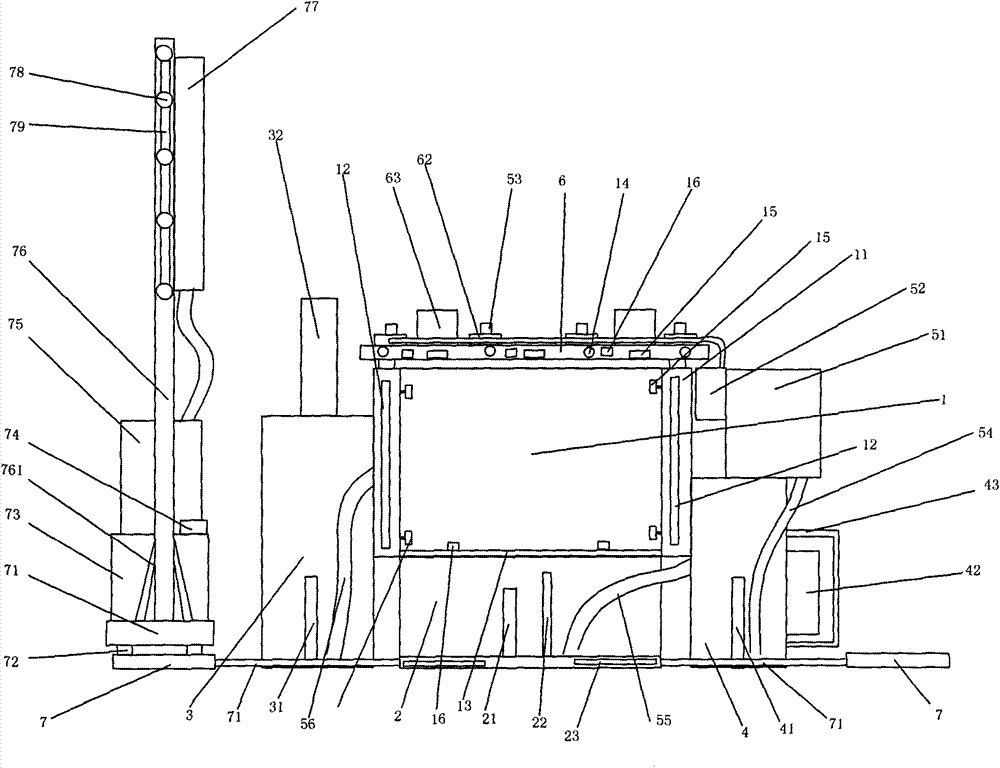
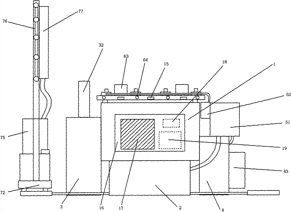
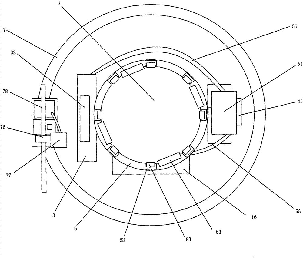
[0028] Embodiment 1: as figure 1 , figure 2 and image 3As shown, a flower pot includes a pot body 1, and the pot body 1 is circular. A rectangular bump 16 is arranged on the basin body 1, and a display screen 17 is arranged on the rectangular bump 16, and the display screen 17 is a touch screen. A single-chip microcomputer 19 and a signal generator 18 are arranged inside the rectangular bump 16 , and the single-chip microcomputer 19 controls the signal generator 18 . A cavity 11 is provided between the outer side wall of the basin body 1 and the inner side wall of the basin body 1, and several first heating resistance wires 12 are arranged in the cavity 11, and the first heating resistance wires 12 can be uniformly distributed in the cavity 11 around the circumference, and also It can be continuously arranged in the cavity 11, and the first heating resistance wire 12 is controlled by a single-chip microcomputer 19. The bottom of the basin body 1 is provided with a liquid...

Embodiment 2

[0034] Embodiment 2: as Figure 4 , Figure 5 and Figure 6As shown, a flower pot includes a pot body 1, and the pot body 1 is circular. A rectangular bump 16 is arranged on the basin body 1, and a display screen 17 is arranged on the rectangular bump 16, and the display screen 17 is a touch screen. A single-chip microcomputer 19 and a signal generator 18 are arranged inside the rectangular bump 16 , and the single-chip microcomputer 19 controls the signal generator 18 . A cavity 11 is provided between the outer side wall of the basin body 1 and the inner side wall of the basin body 1. The cavity 11 is provided with several electromagnets 82. The electromagnets 82 are elongated. The electromagnets 82 are vertically placed in the cavity 11. Inside, and evenly distributed in the circumference of the cavity 11. Several magnets 81 are arranged in the pot body 1, and the magnets 81 can be mixed in the soil. The magnets 81 have no regular arrangement in the soil and can be place...

Embodiment 3

[0038] Embodiment 3: as Figure 7 , Figure 8 and Figure 9 As shown, a flower pot includes a pot body 1, and the pot body 1 is circular. A rectangular bump 16 is arranged on the basin body 1, and a display screen 17 is arranged on the rectangular bump 16, and the display screen 17 is a touch screen. A single-chip microcomputer 19 and a signal generator 18 are arranged inside the rectangular bump 16 , and the single-chip microcomputer 19 controls the signal generator 18 . A cavity 11 is provided between the outer side wall of the basin body 1 and the inner side wall of the basin body 1. Several air outlets 124 are arranged at the upper end of the cavity 11, and several air suction ports 121 are arranged at the lower end, and the air outlets 124 and the air suction ports 121 are uniform. The circumference is disposed within the cavity 11 . Several air suction fans 122 are arranged above the air suction port 121 , and the uniform circumferences of the air suction fans 122 co...


PUM


Abstract

The invention discloses a heat-insulation flowerpot, and relates to the technical field of horticulture. The heat-insulation flowerpot comprises a flowerpot body and a liquid spraying device. A liquid collecting tank is arranged below the flowerpot body, a cavity is arranged between the outer wall and the inner wall of the flowerpot body, first heating resistance wires are arranged in the cavity, a water tank and a fertilizer tank are respectively arranged on two sides of the flowerpot body, a permeable plate is arranged between the flowerpot body and the liquid collecting tank, an ion solubility measuring instrument is arranged in the liquid collecting tank, a display screen and a single chip microcomputer are arranged on the flowerpot body, the single chip microcomputer controls the liquid spraying device and the first heating resistance wires, the ion solubility measuring instrument is connected with the single chip microcomputer, an annular support is arranged on the top of the flowerpot body, a plurality of heat-insulation lamps are arranged on the annular support, and the single chip microcomputer controls the heat-insulation lamps. Compared with the prior art, the heat-insulation flowerpot has the advantages that heat can be automatically generated in winters, so that certain temperature of the heat-insulation flowerpot can be kept, and plants can be prevented from being frozen to death; the problem that southern cold-intolerant plants cannot survive in northern cold environments can be solved.

Description

technical field [0001] The invention relates to the technical field of gardening, in particular to a flower pot. Background technique [0002] At present, as everyone pays more attention to the environment, and at the same time, in order to beautify the indoor environment, they are used to planting plants indoors and outdoors. In today's cities, there are many potted green plants, whether at home or in the office, but due to the busy life and work of urban people and the lack of professional planting knowledge, many plants are often left unattended or will not be taken care of. Reasonable and withered death, resulting in a waste of resources. China has a vast territory and many plant varieties. Different plants have different habits. Most plants have certain regional characteristics. For example, plants living in the south are not suitable for living in the cold climate in the north. To survive in the cold climate of the north, some insulation devices can be added to the f...

Claims


Application Information

Patent Timeline
IPC IPC(8): A01G9/02A01G9/20A01G9/24A01C23/04
CPCY02A40/25
Inventor 金弘毅
Owner QIDONG QINGQING VEGETABLE & FRUIT RURAL LAND STOCK PROFESSIONAL COOP
Why Eureka
Try Eureka