Oil groove processing mechanism of engine bearing

A processing mechanism and oil tank technology, applied in metal processing machinery parts, metal processing equipment, manufacturing tools, etc., can solve problems such as error-prone manual scribing, difficulty in ensuring the machining accuracy of the oil tank, and size deviation of the oil tank in the bearing bush.

Inactive Publication Date: 2014-04-30
重庆信奇建材机械制造有限公司
View PDF0 Cites 2 Cited by
  • Summary
  • Abstract
  • Description
  • Claims
  • Application Information

AI Technical Summary

Problems solved by technology

In the bearing bush parts, it is necessary to open multiple oil grooves with intersection points. The common oil groove processing method is to use manual scribing and then cut on the lathe. The processing defect of this type of lathe is that it needs to be processed multiple times according to the scribing to complete the oil groove. cutting, and manual scribing is prone to errors, it is difficult to ensure the machining accuracy of the oil groove, and it is easy to cause deviations in the size of the oil groove in the bearing bush

Method used


Image

  • Oil groove processing mechanism of engine bearing

Examples


Embodiment Construction

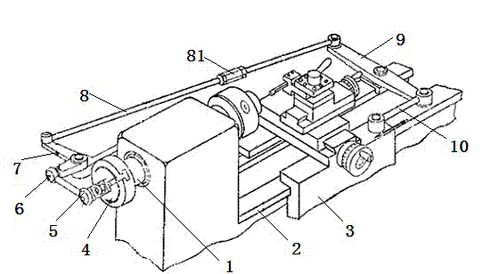
[0009] Such as figure 1 As shown: the bearing bush oil groove processing mechanism is set on a lathe, the front end of the lathe spindle 1 is provided with a chuck for clamping the workpiece, and the lathe slide rail 2 is provided with a turning tool supporting plate 3 opposite to the lathe spindle 1. 1. The disc 4 is coaxially fixed at the end, and the disc 4 has a chute along the radial direction. The cross section of the chute is T-shaped. The bracket 5 has a chuck matching the chute. Sliding in the shaped chute. Bracket 5 is connected with connecting rod mechanism through ball joint 6, and this connecting mechanism is formed by the end-to-end connection of right-angle lever 7, adjusting rod 8, feed rod 9 and connecting rod 10, and elastic turnbuckle 81 is installed on adjusting rod 8 shaft. , turn the turnbuckle 81 to adjust the length of the adjusting rod 8 . The fulcrum of the middle section of the feed rod 9 is fixed on the lathe and is coaxial with the lathe spindle ...


PUM


Abstract

The invention belongs to the technical field of lathe turning and relates to an oil groove processing mechanism. The oil groove processing mechanism is arranged on a turning-lathe. The front end of a main shaft of the turning-lathe is provided with a clamping head of a clamp workpiece, a sliding rail of the turning-lathe is provided with a turning tool plate which is opposite to the main shaft, and a disc is fixed on the tail end of the main shaft in a coaxial manner. The disc is provided with a bracket which slides in a radial direction along the disc and the bracket drives a connecting rod mechanism. The connecting rod mechanism is formed from a bell crank lever, a regulating stem, a feed rod, and a connecting rod which are connected from beginning to end successively, wherein a rigging screw is arranged on the regulating rod, a support point in the center of the feed stem is coaxial with the main shaft of the turning-lathe, and the end of the connecting rod is connected with the turning tool plate.

Description

technical field [0001] The invention belongs to the technical field of turning. Background technique [0002] In construction machinery, many shaft sleeve parts are provided with oil grooves in the inner holes, and the oil grooves are usually in the shape of 8 or double 8. In the bearing bush parts, it is necessary to open multiple oil grooves with intersection points. The common oil groove processing method is to use manual scribing and then cut on the lathe. The processing defect of this type of lathe is that it needs to be processed multiple times according to the scribing to complete the oil groove. It is difficult to ensure the machining accuracy of the oil groove, and it is easy to cause deviations in the size of the oil groove in the bearing pad. Contents of the invention [0003] The present invention intends to provide a bearing pad oil groove processing mechanism with one-time processing and high processing precision. [0004] The purpose of the present inventi...

Claims


Application Information

Patent Timeline
Patent Type & Authority Applications(China)
IPC IPC(8): B23B5/00B23Q5/34
CPCB23B3/06B23B5/00B23Q5/34
Inventor 张信聪
Owner 重庆信奇建材机械制造有限公司
Why Eureka
Try Eureka