
A scr denitrification device

A denitrification and box technology, applied in separation methods, dispersed particle separation, chemical instruments and methods, etc., can solve problems such as high temperature, difficult collection and treatment of reaction products, and inability to ensure complete ammonia reaction, so as to achieve easy collection and avoid Multi-processing, easy to collect and process the effect

Active Publication Date: 2020-05-08
丰城新高焦化有限公司
View PDF3 Cites 0 Cited by
  • Summary
  • Abstract
  • Description
  • Claims
  • Application Information

AI Technical Summary

Problems solved by technology

Although this method can remove nitrogen oxides in industrial waste gas, the traditional SCR denitrification device is no longer fully capable of meeting higher and higher emission requirements. The traditional SCR denitrification device cannot ensure the perfect ratio of ammonia gas to industrial waste gas, and cannot guarantee While the nitrates are removed, the ammonia gas reacts completely, so that it will not be discharged into the atmosphere together with the treated gas; the temperature required for the denitration process of the traditional SCR denitrification device is high, and the reaction product after denitration is not easy to collect and handle

Method used

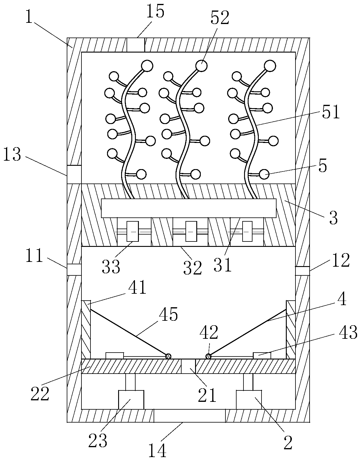

Image

  • A scr denitrification device
  • A scr denitrification device
  • A scr denitrification device

Examples


Embodiment Construction

[0020] In order to make it easy to understand the technical means, creative features, goals and effects achieved by the present invention, the present invention will be further explained in conjunction with specific implementations below.

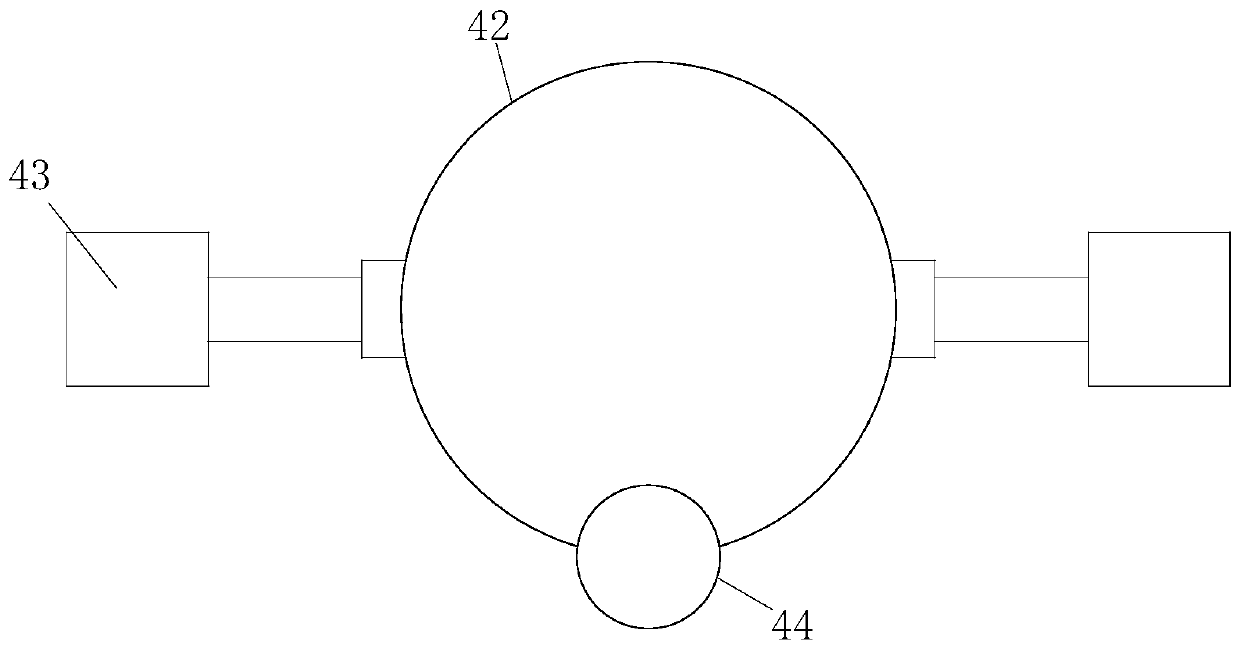
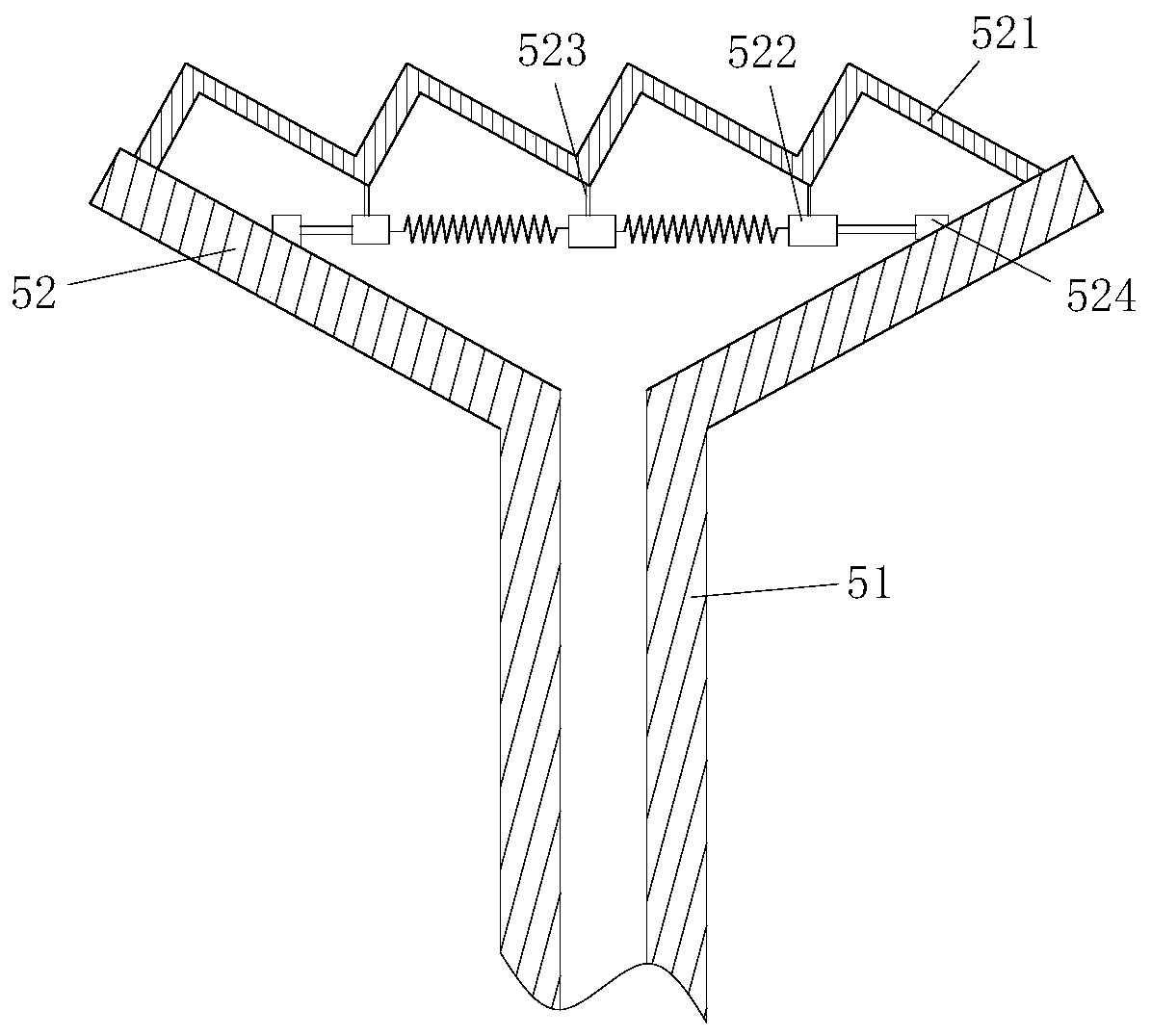
[0021] Such as Figure 1 to Figure 3 As shown, the SCR denitration device according to the present invention includes a box body 1, a push module 2, a fixed plate 3, an adjustment module 4, and a discharge module 5; the push module 2 is located under the box body 1, and the push module 2 It is used to push the reactants in the box 1 into the box 1; the fixed plate 3 is located inside the box 1, and the fixed plate 3 is located above the pushing module 2; the box 1 is provided with an air inlet 11, Ammonia water input port 12, waste liquid discharge port 13, blanking port 14 and gas discharge port 15. The air inlet 11 is located on the left side of the box 1, and the air inlet 11 is located between the push module 2 and the fixed plate 3. The ...


PUM


Abstract

The invention belongs to the technical field of industrial waste gas treatment, and particularly relates to an SCR (Selective Catalytic Reduction) denitrification device. The SCR denitrification device comprises a box body, pushing modules, a fixed plate, adjustment modules and discharging modules, wherein the pushing modules are positioned below the box body; the fixed plate is positioned in thebox body and is positioned above the pushing modules; the box body is provided with an air inlet, an ammonia water input hole, a waste liquid drainage hole, a blanking hole and a gas exhaust hole; theair inlet is positioned on the left side of the box body and is positioned between the pushing modules and the fixed plate; the ammonia water input hole is positioned on the right side of the box body and is positioned between the pushing modules and the fixed plate; the waste liquid drainage hole is positioned in the box body and is positioned above the fixed plate; the blanking hole is positioned at the bottom of the box body and is used for enabling solid residues to be discharged out of the box body; the pushing modules are also provided with a solid residue outlet; the adjustment modulesare positioned in the box body and are fixed to the pushing modules; the discharging modules are positioned in the box body, and the bottom ends of the discharging modules are mounted on the fixed plate.

Description

Technical field [0001] The invention belongs to the technical field of industrial waste gas treatment, and specifically is an SCR denitration device. Background technique [0002] Nitrogen oxide is one of the main pollutants of air pollution. It is also an important factor in the frequent occurrence of haze and meteorological disasters in recent years, which has caused serious harm to the natural environment and human health. With the increasingly severe environmental situation, the state and the government have continuously revised the emission standards of air pollutants, and the control requirements have been continuously improved. From the 2011 "Pollutant Emission Standards for Thermal Power Plants" GB13223-2011 to the later "Energy Conservation and Reduction of Coal Power Emission Upgrade and Renovation Action Plan (2014-2020)", the nitrogen oxide emission requirement of coal-fired units has been further increased from 100mg / Nm3 to the requirement of 50mg / Nm3 for gas-fired u...

Claims


Application Information

Patent Timeline
Patent Type & Authority Patents(China)
IPC IPC(8): B01D53/86B01D53/90B01D53/56
CPCB01D53/8631B01D53/90B01D2251/2062B01D2258/0283
Inventor 朋仁锋
Owner 丰城新高焦化有限公司
Learn More