Flexible hinge and floating frame matched clamping and positioning device for optical component

A technology of flexible hinges and optical components, applied in workpiece clamping devices, manufacturing tools, etc., can solve the problems of rigid connection, the position and posture of optical components cannot meet the repair processing, and accumulated on the air-floating frame, etc., to achieve smooth operation, Reliable large range of motion, compact effect

Active Publication Date: 2014-04-30
HARBIN INST OF TECH
View PDF4 Cites 6 Cited by
  • Summary
  • Abstract
  • Description
  • Claims
  • Application Information

AI Technical Summary

Problems solved by technology

When the air-floating frame is driven by the two-dimensional large-stroke linkage device to realize a large-scale full-stroke movement, it is necessary to ensure that the surface of the optical element and the surface of the working platform have a high degree of parallelism and the distance between the two planes is basically constant during the full-stroke movement. Therefore, the air-floating frame cannot

Method used


Image

  • Flexible hinge and floating frame matched clamping and positioning device for optical component
  • Flexible hinge and floating frame matched clamping and positioning device for optical component
  • Flexible hinge and floating frame matched clamping and positioning device for optical component

Examples


specific Embodiment approach 1

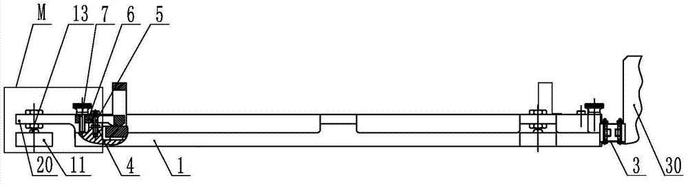
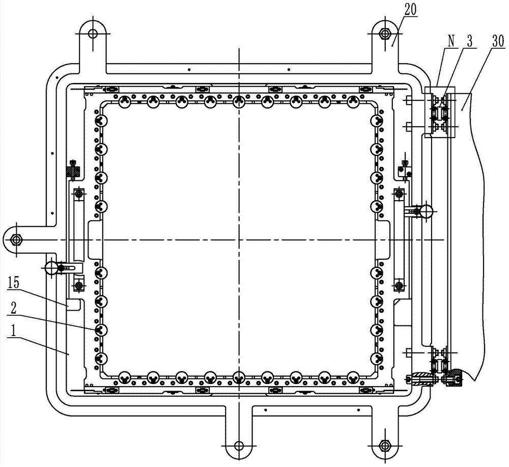
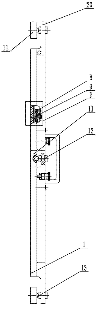
[0020] Specific implementation mode one: combine Figure 1-Figure 22 and Figure 24-Figure 26 Explain that the flexible hinge of this embodiment cooperates with the air-floor frame to be used for clamping and positioning of optical components. Pad 11, three spherical hinge studs 13 and two groups of flexible hinges 3, the air float frame includes a crystal frame 1, two compression blocks 6, two positioning screws one 8, two positioning screws two 7, two Locking block 9, two positioning blocks 15 and five connecting ears 20;

[0021] The crystal frame 1 is a rectangular frame arranged horizontally (it is the main part of the whole device), and two sets of flexible hinges 3 are fixed to the same arbitrary outer surface of the crystal frame 1 (by bolts and nuts); the remaining three of the crystal frame 1 Five connecting ears 20 are fixed on the outer surface, and a positioning block 15 is respectively fixed on two opposite inner surfaces of the crystal frame 1, and a positioni...

specific Embodiment approach 2

[0038] Embodiment 2: The distribution of the five connecting ears 20 in this embodiment on the remaining three outer surfaces of the crystal frame 1 is as follows: One connecting ear 20 is affixed to the outer surface of the crystal frame 1, and two connecting ears 20 are affixed to each outer surface of the crystal frame 1 perpendicular to the side on which two groups of flexible hinges 3 are fixed. The undisclosed technical features in this embodiment are the same as those in the first embodiment.

specific Embodiment approach 3

[0039] Specific embodiment three: the distribution of the five connecting ears 20 in the present embodiment on the remaining three outer surfaces of the crystal frame 1 is as follows: on the crystal frame 1, the side perpendicular to the side where two groups of flexible hinges 3 are fixed Two connecting ears 20 are affixed to one of the two outer surfaces, and a connecting ear is affixed to the other of the two outer surfaces perpendicular to the side on which two groups of flexible hinges 3 are fixed on the crystal frame 1 20. The undisclosed technical features in this embodiment are the same as those in the first embodiment.


PUM


Abstract

The invention discloses a flexible hinge and floating frame matched clamping and positioning device for an optical component. A flexible hinge and a floating frame are matched to be used for clamping and positioning the optical component, so that a large-caliber optical component is provided with the low-stress-strain reliable clamping capacity in the horizontal plane, moreover, the floating frame and two-dimensional large stroke are in flexible connection, so that the parallelism between the optical element surface and the work table plane is guaranteed. The flexible hinge is fixedly connected with a crystal frame, connection lugs are fixed on the crystal frame, positioning blocks are fixed in the crystal frame, and the optical component is disposed in the crystal frame integrally and positioned through the positioning blocks. Locking blocks are fixed in the crystal frame, first positioning screws are screwed in the locking blocks, and the optical component is pre-clamped and fixed between the first positioning screws and the positioning blocks. Compression blocks are fixedly connected with the crystal frame, and the optical component is compressed and fixed vertically through the compression blocks. Spherical hinge studs are fixedly connected with connection lugs and are in contact with air floating pads. The device is used for clamping and positioning of optical elements during micro-defect rapid searching and repairing.

Description

technical field [0001] The invention relates to a flexible hinge matched with an air floating frame for clamping and positioning of optical components. Background technique [0002] In the process of ultra-precision machining and strong laser targeting, the surface of the optical element is prone to produce micro-cracks or ablation pits and other forms of micro-defects on the surface of the optical element due to the fly-cutting process or the impact of the strong laser. The micro-defects on the surface of the component need to be removed as soon as possible in the early stage of forming, otherwise they will grow rapidly during the strong laser targeting process, resulting in damage to the optical component and making it unusable. Since the cost of the optical component is extremely expensive, it will cause great waste. At present, the use of micro-repair methods is proposed to delay the performance and service life of optical components, and a large number of feasibility ex...

Claims


Application Information

Patent Timeline
IPC IPC(8): B25B11/00
CPCB25B11/02
Inventor 陈明君廖然肖勇张文明蒋琳曦左泽轩王健
Owner HARBIN INST OF TECH
Why Eureka
Try Eureka