Passive magnetic suspension type electromagnetic launcher

A magnetic levitation and catapult technology, which is applied in the direction of launch/drag transmission device, can solve the problem of not eliminating the rolling friction resistance of aircraft wheels and deck, and achieve the effects of simple structure, energy saving, and increased ejection speed.

Inactive Publication Date: 2014-04-30
SHANGHAI UNIV
View PDF6 Cites 15 Cited by
  • Summary
  • Abstract
  • Description
  • Claims
  • Application Information

AI Technical Summary

Problems solved by technology

[0008] At present, the United States has successfully used electromagnetic catapults to eject aircraft on land, but the electromagnetic catapults currently developed by the United States only replace the pistons of steam catapults with high-power linear ejection motors. The ejection motors have rollers. A reciprocating vehicle runs along the catapult track under the action of electromagnetic force, pulls the aircraft on the deck and accelerates to take-off speed along the ejection stroke, the aircraft is still placed directly on the deck through the wheels, and the gap between the aircraft wheels and the deck is not eliminated. rolling friction resistance

Method used


Image

  • Passive magnetic suspension type electromagnetic launcher
  • Passive magnetic suspension type electromagnetic launcher
  • Passive magnetic suspension type electromagnetic launcher

Examples


Embodiment 1

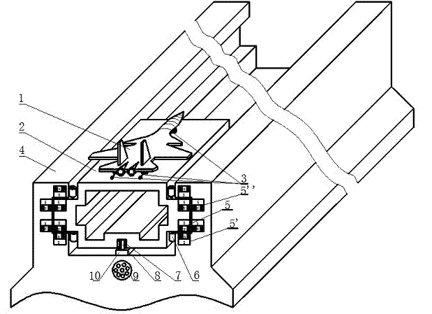
[0027] see Figure 1~Figure 3 , the passive magnetic levitation electromagnetic catapult includes a carrier-based aircraft 1 to be ejected and an ejection platform 2 for placing the carrier-based aircraft and being set on the guide rail, and is characterized in that it also includes a connecting part 3 connected to the carrier-based aircraft 1 on the ejection platform 2 , the ejection base 4 with magnetic levitation guide rails, the permanent magnetic strips A 5 B 5' embedded in the convex strips on both sides of the ejection platform 2 and the upper and lower grooves on both sides of the ejection base 4 respectively, 4 installed on both sides of the ejection platform 2 A guide protection small roller 6 rolls against the inner walls on both sides of the ejection base 4, and is located on the center line of the bottom surface of the magnetic levitation guide rail of the ejection base 4. The primary winding 8 of the linear ejection motor for providing ejection power and is corres...

Embodiment 2

[0029] This implementation example is basically the same as the implementation example 1, and the special features are as follows:

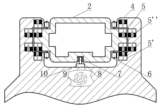
[0030]The described passive magnetic levitation electromagnetic catapult is characterized in that the permanent magnetic bar armor 5 installed on the ejection platform 2 forms a magnetic levitation support device, and the device adopts repulsive magnetic levitation technology, corresponding to the same section of the ejection platform 2, the ejection base 4 A pair of repulsion-supported bearing permanent magnet strips B 5' are respectively installed on the two sides and below of the magnetic levitation guide rail, and a pair of repulsion-supported guide permanent magnet strips C 5'' are respectively installed on both sides and bottom of the guide rail. The difference of the active magnetic levitation technology is that it does not require a control circuit; the primary winding 8 of the linear ejection motor is installed in the middle of the magnet...

Embodiment 3

[0035] see figure 1 and figure 2 , the passive magnetic levitation electromagnetic catapult includes a carrier-based aircraft 1 to be ejected and an ejection platform 2 for placing the carrier-based aircraft and being set on the guide rail, and is characterized in that it also includes a connecting part connected to the carrier-based aircraft 1 on the ejection platform 2 3. Ejection base 4 with magnetic levitation guide rails. The permanent magnetic strips A 5 and B 5' embedded in the upper and lower grooves on both sides of the ejection base 4 and the convex strips on both sides of the ejection platform 2 are installed on both sides of the ejection platform 2. The guide protection roller group 6 used to prevent the contact between the platform 2 and the inner walls on both sides of the base 4, the linear ejection motor primary winding 8 located on the ejection base 4 corresponding to the center line of the bottom surface of the ejection platform to provide ejection power, an...


PUM


Abstract

The invention relates to a passive magnetic suspension type electromagnetic launcher for aircraft carriers. The passive magnetic suspension type electromagnetic launcher comprises a fixed launch base, a launch platform, and a linear motor; the launch platform and the linear motor are enclosed in the launch base. The carrier-based aircraft launch platform is supported by the passive magnetic suspension bearing technology; the launch platform is driven by a high-power linear launch motor, so that catapult-assisted take-off of the carrier-borne aircraft is achieved. Compared to the prior art, the passive magnetic suspension type electromagnetic launcher has the advantages that the passive magnetic suspension bearing technology is introduced, a speed control system is provided, precision and catapulting speed are greatly increased, electrification is achieved, catapulting distance is shortened, the service life is prolonged, and the launcher is friction free, energy saving, simple in structure, lubrication free, free of environmental pollution and the like.

Description

technical field [0001] The invention relates to an electromagnetic catapult used on an aircraft carrier, in particular to a passive magnetic levitation electromagnetic catapult. Background technique [0002] As the overlord of the sea, the aircraft carrier occupies a central position in naval weapons. The catapult, one of the key components of an aircraft carrier, has always been a major difficulty in aircraft carrier technology. With the rapid growth of our country's economy and the continuous improvement of the level of science and technology, our country already has certain economic strength and technical capabilities to develop its own aircraft carrier. The Liaoning ship aircraft carrier converted from the Varyag is the real starting point of China's aircraft carrier, but it is refitted from an unfinished aircraft carrier bought by our country from Ukraine. There are no key components including catapults at all, only relatively backward slides Leap to help take off the...

Claims


Application Information

Patent Timeline
Patent Type & Authority Applications(China)
IPC IPC(8): B64F1/06
Inventor 张钢张海龙张坚支汉立姜笑颖孟庆涛刘飞倪晓艇朱琳
Owner SHANGHAI UNIV
Why Eureka
Try Eureka