Convenient water-saving all-composite nano-filtration and reverse osmosis water purifier

A water-saving, reverse osmosis technology, applied in water/sewage multi-stage treatment, water/sludge/sewage treatment, chemical instruments and methods, etc., can solve problems such as waste of water resources, loose structure, and large dimensions. Achieve the effect of convenient installation, convenient installation and compact structure

Inactive Publication Date: 2014-04-30
饶桂华
5 Cites 29 Cited by

AI-Extracted Technical Summary

Problems solved by technology

The quality water supply machine is usually equipped with a water inlet ball valve, a booster pump, a pressure storage tank, an outlet faucet and several stages of filters, such as polypropylene filters, granular activated carbon filters, extruded activated carbon rod filters, reverse osmosis or nanofiltration Filters and electrical control parts, each filter is independent, electrical control parts (including low pressure switch, high pressure switch, water inlet solenoid valve, flushing solenoid valve, booster pump and transformer, waste water proportioner, etc.) and filter elements Interlaced assembly, they are connected with each other by multi-section pipes and pipe joints according to the filtration process, through different collocations to form mult...

Method used

The filtration process of this convenient water-saving type full composite nanofiltration 3 and reverse osmosis water purifier is as follows: as shown in Figure 1, tap water enters water intake through water inlet joint 13, miniature booster pump 8 and water inlet channel 165 Cavity 15, the micro booster pump 8 pressurizes the influent water flow, and then passes through the sedimentation filter layer 1 and the activated carbon filter layer 2 successively, enters the gap between the activated carbon filter layer 2 and the nanofiltration layer 3, and goes up to the nanofiltration layer 3 Part of the water flows ...

Abstract

The invention relates to a convenient water-saving all-composite nano-filtration and reverse osmosis water purifier. The convenient water-saving all-composite nano-filtration and reverse osmosis water purifier comprises a shell, a filter element and a micro booster pump, wherein a clean water outlet nozzle is arranged on the shell; the filter element and the micro booster pump are arranged in the shell; the filter element is a composite filter element; the composite filter element adopts a cylindrical and radial multi-layer composite structure; a filter element seat is arranged in the shell; the composite filter element is arranged on the filter element seat in the shell; a space is reserved in the outer wall of the composite filter element to form a water inlet cavity; a water outlet cavity is separated from the water inlet cavity by a filter layer of the composite filter element; a water inlet connector and a washing water connector are also arranged on the shell. According to the convenient water-saving all-composite nano-filtration and reverse osmosis water purifier, the composite filter element with a multi-layer filter layer is arranged in the shell, so that the structure is compact, the volume is small, the water purifier is mounted at the required placed and is mounted without help of professionals; meanwhile, the washing water connector is arranged, so that waste water can be recovered and recycled to fulfill the aim of saving water.

Application Domain

Technology Topic

Image

  • Convenient water-saving all-composite nano-filtration and reverse osmosis water purifier
  • Convenient water-saving all-composite nano-filtration and reverse osmosis water purifier
  • Convenient water-saving all-composite nano-filtration and reverse osmosis water purifier

Examples

  • Experimental program(1)

Example Embodiment

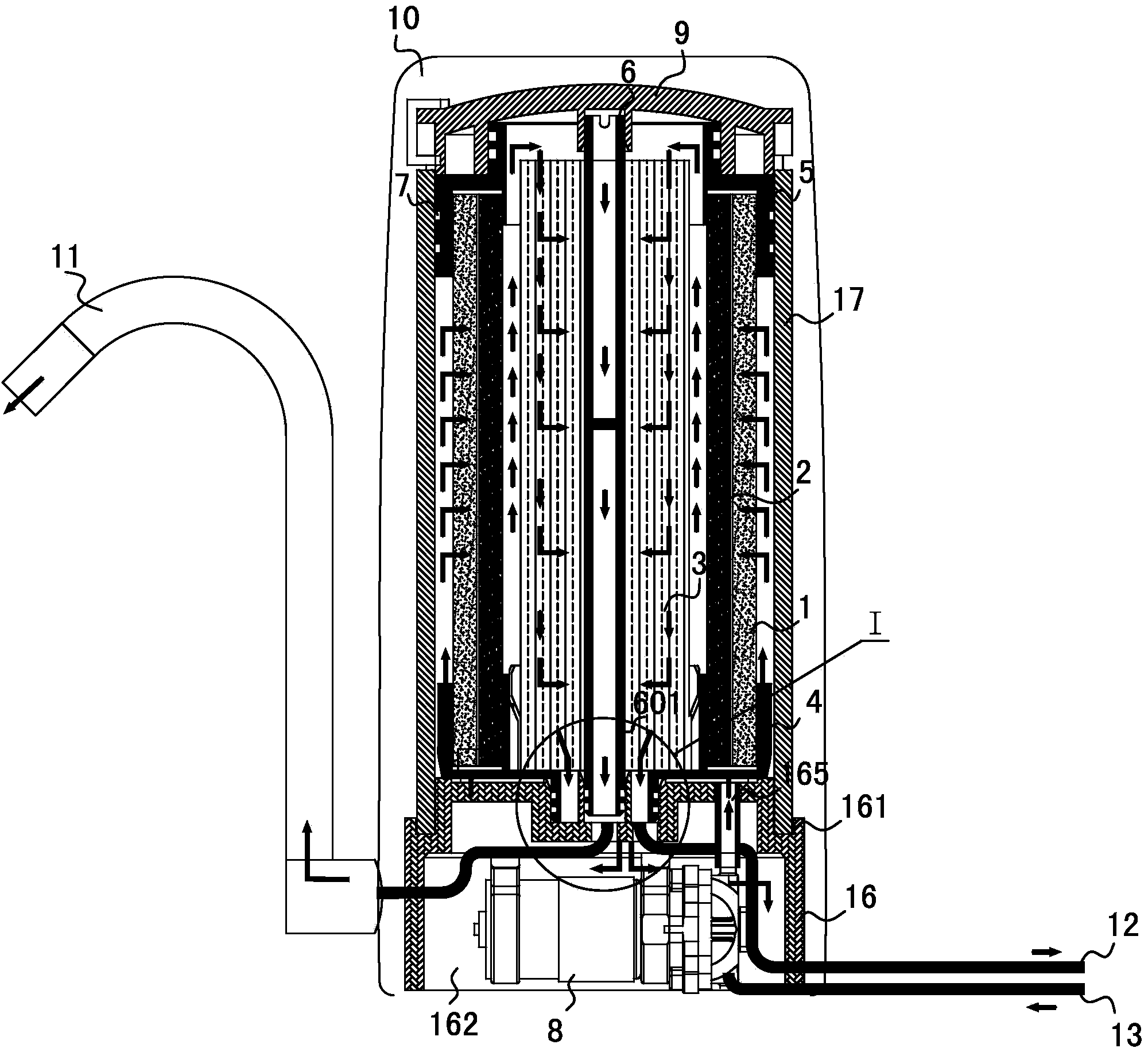
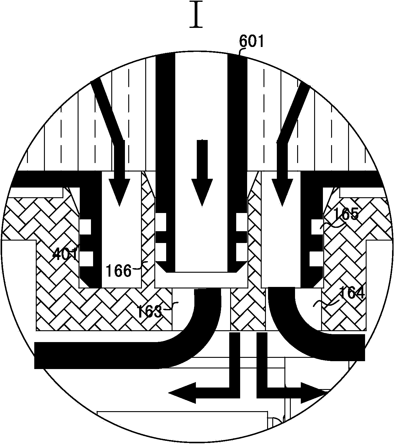
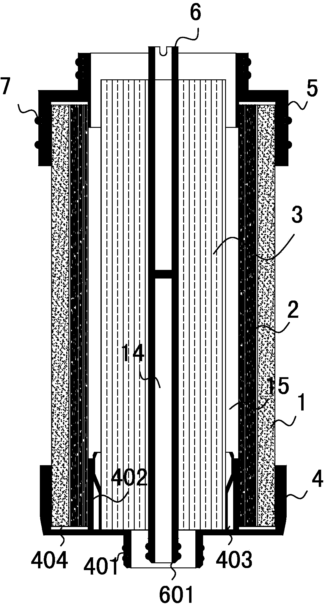
[0010] Such as figure 1 As shown, the convenient water-saving full-composite nanofiltration and reverse osmosis water purifier includes a housing 10, a filter element and a micro booster pump 8. The housing 10 is provided with a water purification nozzle 11, and the filter element and the micro booster pump 8 are arranged in the housing 10. In order to achieve the same filtering effect as the existing household quality water supply machine or water purifier, the structure is compact , The filter element is a composite filter element, the composite filter element is a columnar, radial multi-layer composite structure, the composite filter element is provided with a water outlet cavity 14 in the center and axial direction, and the composite filter element is a precipitation filter element layer 1 from the outside to the inside. Activated carbon filter layer 2 and high-flux nanofiltration 3 or reverse osmosis filter layer (filtration capacity not less than 400 gallons/24h or 1.2L/min), thus simplifying the traditional filtration system controlled by a series of complex linkage programs into straight-in and straight-out The direct-flow water purification system. The housing 10 is provided with a filter element seat 16, the composite filter element is arranged on the filter element seat 16 inside the housing 10, the outer wall of the composite filter element leaves a space to form a water inlet cavity 15, the water outlet cavity 14 and the water inlet cavity 15 Is separated by the filter layer of the composite filter element, the housing 10 is also provided with a water inlet connector 13 and a washing water connector 12, and the filter element seat 16 is provided with a water outlet cavity 14, a water inlet cavity 15 and a composite filter element. The water outlet channel 163, the water inlet channel 165, and the waste water channel 164 connected with the end faces are provided between the water outlet channel 163, the water inlet channel 165 and the waste water channel 164 respectively and the water purification outlet nozzle 11, the water inlet connector 13 and the washing water connector 12 There are pipeline connections.
[0011] Such as figure 1 , 2 As shown, the composite filter element may have a multi-layer plate structure, which filters from one side to the other. In order to make the water purifier structure more compact, in this specific embodiment, as figure 2 As shown, the composite filter element is preferably cylindrical, and the precipitation filter element layer 1, the activated carbon filter element layer 2, and the high-flux nanofiltration 3 or reverse osmosis filter layer form a cylindrical structure (3 layers of nanofiltration are selected in this specific embodiment) , The innermost nanofiltration 3 filter layer is provided with through holes in the center axis, the precipitation filter core layer 1 can be a gradient PP cotton core layer, and the activated carbon filter core layer 2 can be a PE activated carbon composite sintered filter core layer.
[0012] Such as image 3 As shown, the composite filter element is further provided with an upper end cover 5 and a lower end cover 4. The upper end surface of the lower end cover 4 is provided with an inner concave cavity matching the outer diameter of the lower end of the composite filter element. A circle of partitions 402 is provided to divide the inner concave cavity into an inner filter element positioning cavity 403 and an outer filter element positioning cavity 404. The diameter of the area enclosed by the partition 402 matches the diameter of the nanofiltration layer 3, and the lower end of the nanofiltration 3 is fixedly inserted Set in the inner filter element positioning cavity 403, the lower end of the precipitation filter element layer 1, the activated carbon filter element layer 2 is fixedly inserted in the outer filter element positioning cavity 404, and the lower end of the lower end cover 4 is provided with a protruding annular joint 401. The center of the annular joint 401 is provided with an axial through hole communicating with the inner filter element positioning cavity 403; the upper end cover 5 is provided with an inner concave cavity matching the outer diameter of the upper end of the composite filter element, the upper end cover 5 and the lower end cover 4 The fixed covers are respectively arranged on the upper and lower ends of the composite filter element. The central axial through hole of the composite filter element is fixed with a water outlet pipe 6, and the pipe wall of the water outlet pipe 6 is provided with a guide hole to communicate with the inner wall of the 3 layers of nanofiltration. .
[0013] The composite filter element is also provided with a filter element housing 17 and a filter element cover 9. The filter element housing 17 is cylindrical, and the inner diameter of the filter element housing 17 matches the outer diameter of the upper end cover 5 and the lower end cover 4, The composite filter element is arranged in the filter element housing 17, and the outer surface of the upper end cover 5 is provided with a sealing ring 7 which is closed and matched with the inner wall of the upper end of the filter element housing 17, so that the inner wall of the filter element housing 17 and the outer wall of the composite filter element The space constitutes the water inlet cavity 15, the filter element cover 9 closes the upper end of the filter element housing 17 on the upper end cover 5, and the lower end cover 4 is provided with a pipeline communicating with the water inlet cavity 15; The filter element seat 16 is preferably circular truncated, the center of the upper end surface is provided with an insertion cavity 165 formed by a cavity matching the annular joint 401, and the outer circular surface of the filter element seat 16 is provided with an annular shape matching the end surface of the filter element housing 17 The positioning groove 161, the composite filter element is arranged on the filter element seat 16 through the cooperation of the filter element housing 17 and the lower end cover 4 with the filter element seat 16. The other side of the filter element seat 16 is provided with a micro booster pump cavity 162, and a micro booster The pump 8 is arranged in the micro booster pump cavity 162. A tubular catheter socket 166 is provided in the insertion cavity 165 at a position corresponding to the end of the water outlet pipe 6. The tubular pipe socket 166 divides the insertion cavity 165 into a water outlet area and a water return area, and the water outlet area is in the catheter In the socket 166, a water outlet passage is formed between the annular joint 401 and the inner wall of the water outlet pipe 6, and a through hole is provided at the bottom to form a water outlet channel 163. The socket 166 is sealed and plugged in, and a communication pipe is provided between the water outlet hole and the water purification outlet nozzle 11; a through hole is provided at the bottom of the backwater area of ​​the filter element seat 16 to form the wastewater channel 164, and the wastewater channel 164 There is a pipeline connection with the washing water connector 12.
[0014] The filtration process of this convenient water-saving full composite nanofiltration 3 and reverse osmosis water purifier is as follows: figure 1 As shown, tap water enters the water inlet cavity 15 through the water inlet connector 13, the micro booster pump 8 and the water inlet channel 165. The micro booster pump 8 pressurizes the inlet water flow, and then passes through the precipitation filter layer 1 and the activated carbon filter core layer. 2’s filtration enters the gap between the activated carbon filter layer 2 and the nanofiltration layer 3 and goes up to the upper end surface of the nanofiltration layer 3. Part of the water flow is radially filtered through the nanofiltration layer 3 to become purified water and enters the water outlet cavity 14, and then passes through the The outlet hole, the connecting pipe and the water purification outlet nozzle 11 are for standby; the other part of the wastewater flows through the 3 layers of nanofiltration and flows out from the other end of the 3 layers of the nanofiltration into the wastewater channel 164, and then passes through the wastewater channel 164 and the wash water connector 12 The pipelines between the wash water joints 12 return to be reused as wash water, saving water resources.

PUM

no PUM

Description & Claims & Application Information

We can also present the details of the Description, Claims and Application information to help users get a comprehensive understanding of the technical details of the patent, such as background art, summary of invention, brief description of drawings, description of embodiments, and other original content. On the other hand, users can also determine the specific scope of protection of the technology through the list of claims; as well as understand the changes in the life cycle of the technology with the presentation of the patent timeline. Login to view more.

Similar technology patents

Municipal solid waste comprehensive treatment and recycling device

InactiveCN102039303AReduce the spread of odorsCompact structureSievingScreeningWater pipeMetal recycling
Owner:HENAN AOSI ENVIRONMENTAL PROTECTION MACHINE

Classification and recommendation of technical efficacy words

  • Compact structure
  • Reduce volume

Implant release mechanism

ActiveUS20080140178A1Reduce volumeReduce outer diameterStentsOcculdersDilatorStent
Owner:COOK MEDICAL TECH LLC

Flash storage chip and flash array storage system

ActiveUS20080052451A1Reduce volumeImprove data transmission rateMemory adressing/allocation/relocationData transmissionPCI Express
Owner:PHISON ELECTRONICS

Devices and methods for placement of partitions within a hollow body organ

InactiveUS20070167960A1Reduce volumeSuture equipmentsStapling toolsTissue acquisitionBody organs
Owner:ETHICON ENDO SURGERY INC
Why Eureka
Try Eureka