

Lattice type steel reinforced concrete superposed beam
A steel-reinforced concrete, lattice-type technology, applied in the direction of structural elements, building components, building structures, etc., can solve the problems of beam height affecting building clearance, failure to have bearing capacity, etc.
- Summary
- Abstract
- Description
- Claims
- Application Information
AI Technical Summary
Problems solved by technology
Method used
Image

Examples
Embodiment 1
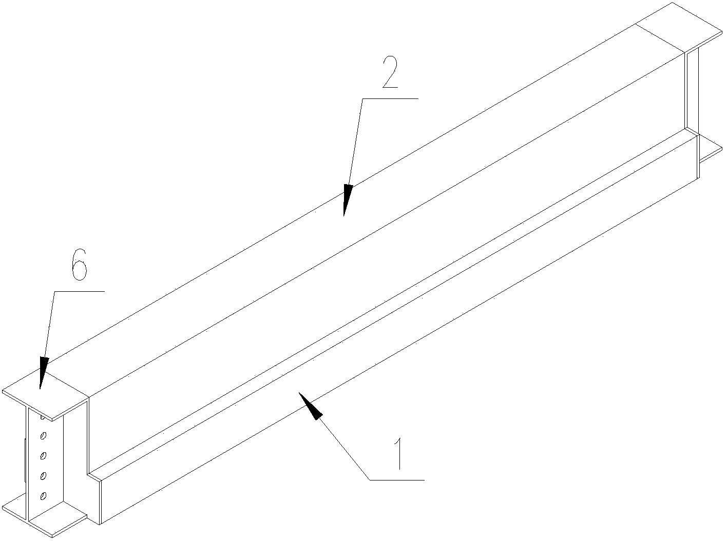
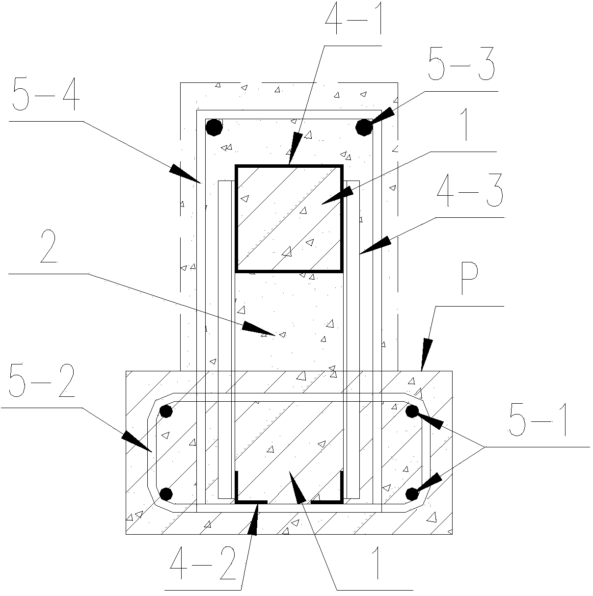
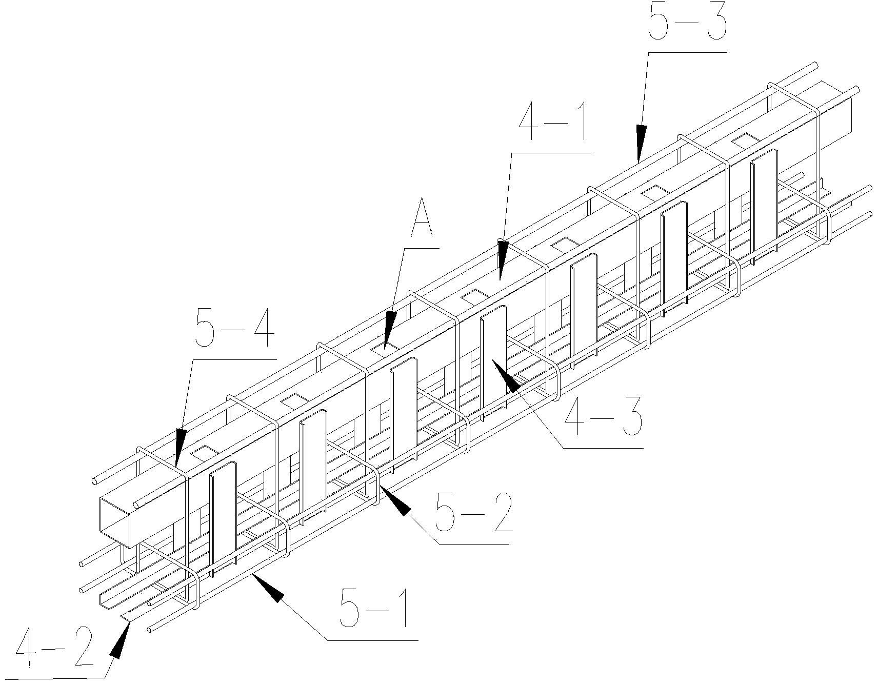
[0017] Embodiment 1 (see attached Figure 1-4 )
[0018] A lattice-type steel-reinforced concrete composite beam of the present invention is composed of a lattice-type steel skeleton 3, a prefabricated lattice-type steel-frame concrete lower beam 1 and a cast-in-place lattice-type steel-frame concrete upper beam 2, and the prefabricated lattice The structural steel skeleton is composed of combined section steel and steel bars; the combined section steel is composed of the upper square steel pipe 4-1, the bottom angle steel 4-2 and the U-shaped steel 4-3 on both sides of the middle part, and the upper reinforcement 5-3 is distributed in the combined section steel above, the lower steel bar 5-1 is correspondingly set on the lower outside of the U-shaped steel 4-3 on both sides of the middle part, and the vertical inner steel bar hoops 5-4 are arranged at intervals, bypassing the upper steel bar 5-3 of the combined section steel and the bottom angle steel 4-2 , hooped to form a ...
Embodiment 2
[0022] A lattice-type steel-reinforced concrete composite beam of the present invention is composed of a prefabricated lattice-type steel skeleton 3, a prefabricated lattice-type steel-reinforced concrete lower beam 1 and a cast-in-place lattice-type steel-reinforced concrete upper beam 2, the prefabricated The lattice steel skeleton is composed of combined section steel and steel bars; the combined section steel is composed of the upper square steel pipe 4-1, the bottom flange plate 4-2 and the middle perforated web 4-3, and the upper steel bars 5-3 are distributed Above the composite section steel, the lower reinforcing bars 5-5 and 5-1 are respectively arranged under the bottom flange plate 4-2, and the outer side of the lower part of the middle perforated web 4-3, and the vertical inner reinforcing bars 5-4 are arranged at intervals, Bypass the steel bar 5-3 above the composite section steel and the reinforcement bar 5-5 below the bottom flange, and hoop to form a cage; the...
PUM
 Abstract
Description
Claims
Application Information