Integrated internally-installed forced wet-type self-locking cycloid hydraulic motor structure

A cycloidal hydraulic motor, self-locking technology, applied in the field of machinery, can solve the problems of failure of the locking function, inability to respond quickly, and short service life of the hydraulic motor, and achieve the purpose of reducing the use requirements, increasing the use range, and reducing the opening pressure. Effect

Inactive Publication Date: 2014-04-30
SHANDONG RNOMAC HYDRAULIC MACHINERY
View PDF6 Cites 2 Cited by
  • Summary
  • Abstract
  • Description
  • Claims
  • Application Information

AI Technical Summary

Problems solved by technology

When the hydraulic motor realizes locking and unlocking, it needs to push the entire brake cylinder to move up and down. Due to the large volume and heavy weight of the brake cylinder, the brake spring needs to have a large pre-tightening force when locking. When unlocking the brake mechanism, it is necessary to use high-pressure oil to overcome the pressure of the brake spring and the self-weight of the brake cylinder to restore the gap d between the dynamic friction plate and the static friction plate to achieve unlocking, so that the self-locking mechanism of the hydraulic motor requires high operating conditions and low volume. It is relatively large, cannot respond quickly and has a certain hysteresis; at the same time, when the locking and unlocking are completed, the dynamic friction plate and the static friction plate are only dry friction without oil lubrication, and the noise is relatively large during use. In addition, because there is no oil directly Lubricate the dynamic friction plate and the static friction plate, the wear of the dynamic friction plate and the static friction plate is relatively fast, so that the service life of the entire hydraulic motor is relatively short, and there is a problem of invalidating the locking function, which poses a safety hazard

Method used


Image

  • Integrated internally-installed forced wet-type self-locking cycloid hydraulic motor structure
  • Integrated internally-installed forced wet-type self-locking cycloid hydraulic motor structure
  • Integrated internally-installed forced wet-type self-locking cycloid hydraulic motor structure

Examples


Embodiment Construction

[0025] The technical scheme of the present invention will be described in detail below in conjunction with the accompanying drawings.

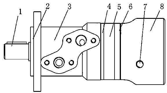
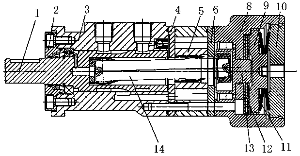
[0026] see Figure 1 to Figure 5 , the hydraulic motor in the embodiment of the present invention takes a cycloidal hydraulic motor as an example, including a power mechanism and a self-locking mechanism, wherein the power mechanism includes an output shaft 1, a linkage shaft 14, and a stator and rotor pair 5. When hydraulic oil enters, The stator-rotor pair 5 starts to rotate and drives the linkage shaft 14 to rotate, and the linkage shaft 14 drives the output shaft 1 to rotate to make the output shaft 1 output torque outward. A housing 3 is arranged outside the output shaft 1, and the front end of the housing 3 is passed through the bolt A front cover 2 is connected, a front partition 4 is provided between the casing 3 and the stator and rotor pair 5, and a rear partition 6 is provided between the stator and rotor pair 5 and the self-locking...


PUM


Abstract

The invention relates to an integrated internally-installed forced wet-type self-locking cycloid hydraulic motor structure. The integrated internally-installed forced wet-type self-locking cycloid hydraulic motor structure is characterized in that a self-locking mechanism comprises a self-locking oil cylinder shell, the rear end of the self-locking oil cylinder shell is provided with a rear cover, a self-locking piston is arranged in the self-locking oil cylinder shell, one side of the self-locking piston and the self-locking oil cylinder shell form a sealing cavity, a self-locking friction plate pair is arranged in the sealing cavity and comprises a static friction plate and a movable friction plate, the static friction plate is connected to the self-locking oil cylinder shell, the movable friction plate is connected to a self-locking main shaft which is connected to a universal driving shaft, the other side of the self-locking piston and the rear cover form a cavity, a compressed spring is arranged in the cavity, a shuttle valve is arranged on the outer surface of the self-locking oil cylinder shell; an oil port I, an oil port II and an oil port III are formed in the shuttle valve; the oil port I and the oil port II are communicated with a stator-rotor pair through an oil channel, and the oil port III is communicated with the sealing cavity through the oil channel. The self-locking oil cylinder shell has the advantages of simple structure, small size, long service life, good reliability and low noise.

Description

technical field [0001] The invention belongs to the mechanical field, and in particular relates to an integrated built-in forced wet self-locking cycloidal hydraulic motor structure. Background technique [0002] In order to achieve the locking function, the existing hydraulic motors mostly adopt the following two methods: one is to add a driving part that can lock the motor. This method will cause complicated installation process, large locking parts, expensive cost and noise. Large size and short service life. At the same time, due to the limitation of installation space and self-weight, it is difficult to realize convenient locking control, which brings inconvenience to users. The second is to rely on the cooperation of its own parts to realize the locking function. Finally, due to the wear and tear between the parts, the locking function will be invalid, and there is a serious potential safety hazard. [0003] The closest existing technology to this patent application i...

Claims


Application Information

Patent Timeline
Patent Type & Authority Applications(China)
IPC IPC(8): F03C2/00
Inventor 郭福光化金明李国良刘宝才田海申
Owner SHANDONG RNOMAC HYDRAULIC MACHINERY
Why Eureka
Try Eureka