
An electromagnetic switching valve

An electromagnetic switching valve and valve body technology, which is applied to the valve details, valve device, valve housing structure, etc., can solve the problems of weak coordination stability of the control valve body 2, complex riveting process, and low riveting efficiency, so as to avoid positioning Unstable offset, reduced production cost, and improved production efficiency

Active Publication Date: 2016-01-20
ZHUHAI HUAYU METAL
View PDF6 Cites 0 Cited by
  • Summary
  • Abstract
  • Description
  • Claims
  • Application Information

AI Technical Summary

Problems solved by technology

The existing fixed frame 6 is riveted at both ends, which has technical problems such as large riveting deformation and complicated riveting process, and the cooperation stability with the control valve body 2 is weak, the riveting efficiency is low, and the processing cost is high

Method used


Image

  • An electromagnetic switching valve
  • An electromagnetic switching valve
  • An electromagnetic switching valve

Examples


Embodiment 1

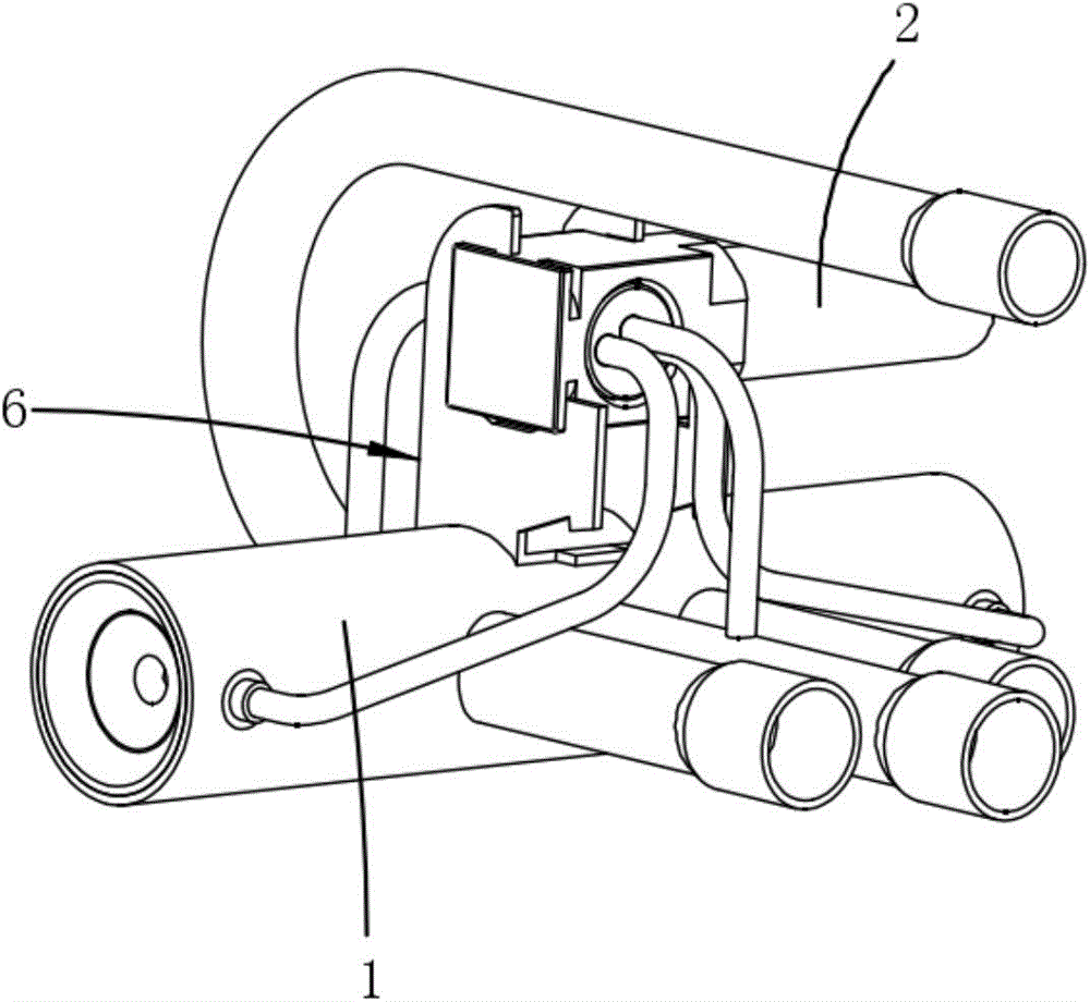
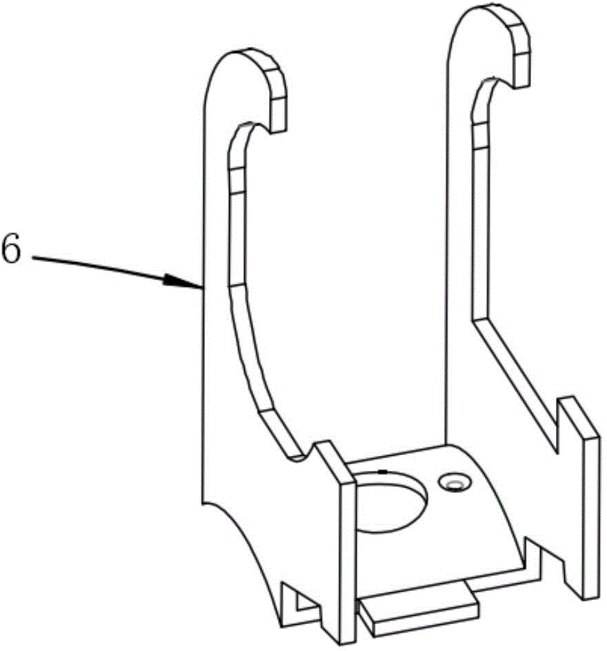
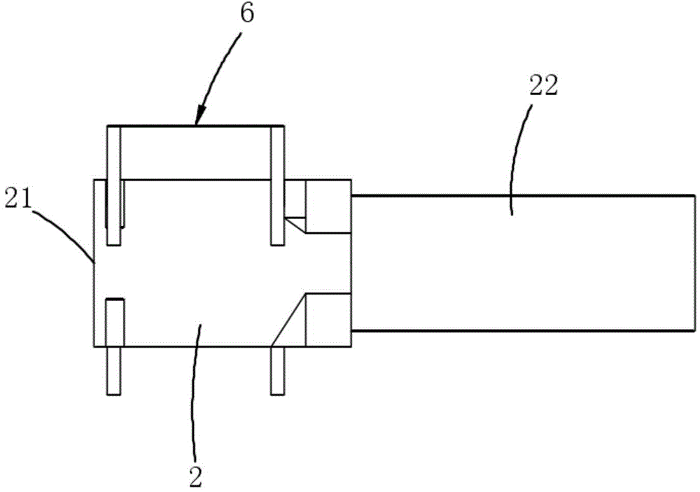
[0023] Example 1, see Figure 4 to Figure 6 Shown: an electromagnetic switching valve, including a main valve body 1, a control valve body 2 and a fixed frame 6 punched and formed by an integral die. The connecting bracket 4, the second side are provided with a round hole fixing frame 5, the buckle type fixing frame 3 and the round hole fixing frame 5 stand upright on both sides of the connecting bracket 4 respectively, the buckle type fixing frame 3, the connecting bracket 4 and the round hole The fixing frame 5 is connected into one body, the connecting bracket 4 is fixed on the main valve body 1, the side of the control valve valve body 2 close to the valve body end 21 is pierced through the round hole fixing frame 5, and the other side of the connecting conduit 22 is fixed on the Buckle mount 3.

[0024] The buckle-type fixing frame 3 includes a first sheet, the lower end of which is connected to the connecting bracket 4, and a buckle with one side opening is punched out ...


PUM


Abstract

The invention discloses an electromagnetic changeover valve. According to the electromagnetic changeover valve, the first side of a fixing frame is provided with a retaining ring type fixing frame body, the middle of the fixing frame is provided with a connecting support, and the second side of the fixing frame is provided with a round hole fixing frame body. The retaining ring type fixing frame body, the connecting support and the round hole fixing frame body are connected into one. The connecting support or the retaining ring type fixing frame body is fixed to a main valve body. One side, close to the end portion of the valve body, of the valve body of a control valve is arranged in the round hole fixing frame body in a penetrating mode, and the other side connected with a guide pipe is fixed to the retaining ring type fixing frame body. The electromagnetic changeover valve avoids the problem that due to poor deformation of the fixing frame and unstable location shift in the riveting process, products are not good, lowers the complexity of the riveting process, and greatly improves the production efficiency, the utilization rate of raw materials of the valve body of the control valve is reduced, the installation height of the valve body of the control valve and the main valve body is ensured, the performance consistence of the products is improved, and the production cost is lowered.

Description

Technical field: [0001] The invention relates to the technical field of electromagnetic switching valves used in the air-conditioning and refrigeration industry, in particular to an electromagnetic switching valve. Background technique [0002] Electromagnetic switching valve is an important part of heat pump air conditioner, suitable for central and split air conditioners, etc. The action of the existing electromagnetic switching valve is to use the high and low pressure difference in the system, and use the switching of the electromagnetic coil of the control valve to switch the flow path of the main valve body 1, and then realize the change of the refrigerant flow direction in the system. The control valve is connected with the main valve body 1 through a fixing bracket 6 . The existing fixing frame 6 is riveted at both ends, which has technical problems such as large riveting deformation and complicated riveting process, and the cooperation stability with the control va...

Claims


Application Information

Patent Timeline
Patent Type & Authority Patents(China)
IPC IPC(8): F16K51/00F16K31/06
CPCF16K27/00F16K31/06F16K51/00
Inventor 熊额江德谭志
Owner ZHUHAI HUAYU METAL
Learn More