
Modularized combination ceiling lamp

A ceiling lamp, modular technology, applied in lighting and heating equipment, semiconductor devices of light-emitting elements, point light sources, etc., can solve problems such as hidden safety and quality, poor flexibility, copper-clad cracking, etc., to achieve convenient maintenance, Improved assembly efficiency, high versatility, and high compatibility

Active Publication Date: 2014-04-30
SHENZHEN CHENGSHENG NEW ENERGY TECH +1
View PDF5 Cites 7 Cited by
  • Summary
  • Abstract
  • Description
  • Claims
  • Application Information

AI Technical Summary

Problems solved by technology

[0003] There are many problems in the production and manufacture of the existing LED ceiling lamps. First of all, when the components that make up the lamps, such as the housing, lampshade, PCB, and LEDs, are assembled, the product combination method and assembly method are not considered in detail in the design. In terms of technology, etc., it is assembled in a way of assembling parts, which makes the assembly process cumbersome when using components such as housings, lampshades, PCBs, and LEDs, and additional screws are used to fix the parts. The production and assembly efficiency is high, and the cost is high; secondly, the existing LED ceiling lamp has a single overall structure, cannot choose to adjust the power, has poor flexibility, single style, and there is not much choice for consumers in terms of specifications and series; moreover, the current In some LED ceiling lamps, different PCBs and LEDs are connected by wire bonding to realize the conduction of the circuit. The wire bonding process is tedious and complicated, and it is prone to desoldering, loose soldering, and copper clad cracking during the assembly process. , there are many safety and quality risks

Method used


Image

  • Modularized combination ceiling lamp
  • Modularized combination ceiling lamp
  • Modularized combination ceiling lamp

Examples


Embodiment Construction

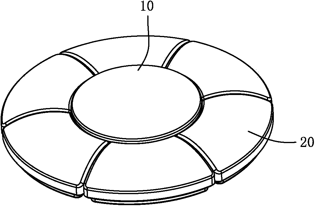
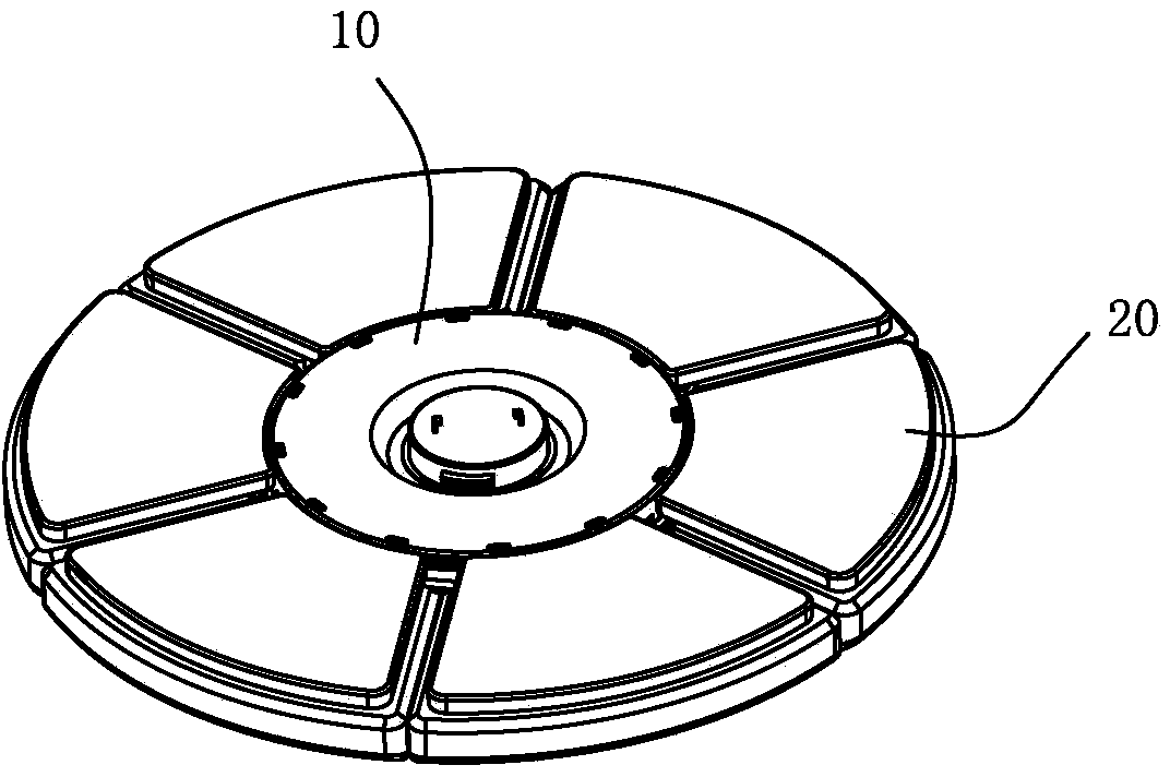
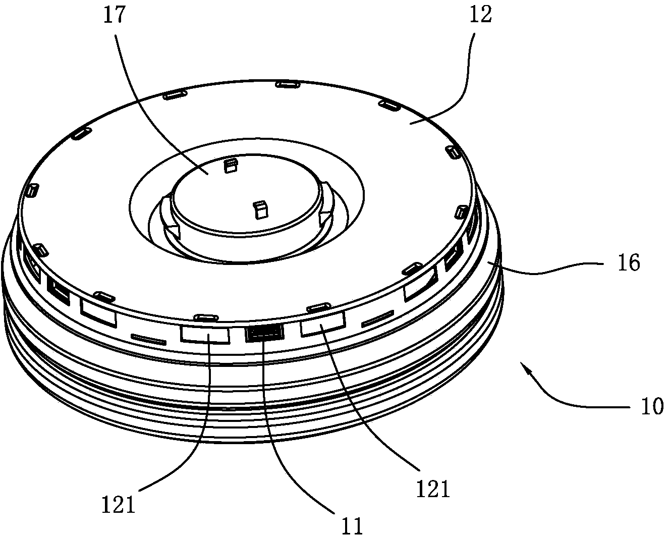
[0024] refer to Figure 1 to Figure 7 , a combined modular ceiling lamp of the present invention, comprising a central light source module 10 and a plurality of edge light source modules 20 arranged at intervals along the circumferential direction outside the central light source module 10, each of the edge light source modules 20 has a USB connector 21 The central light source module 10 is arranged at intervals along the circumferential direction with a plurality of USB interfaces 11 for inserting the USB connectors 21 .

[0025] This combined modular ceiling lamp can be used independently by setting the central light source module 10 as the basic unit ceiling lamp; meanwhile, a plurality of edge light source modules 20 are connected outside the central light source module 10 as auxiliary unit ceiling lamps, and different lamps can be used according to the selection requirements. A number of edge light source modules 20 are combined with a single central light source module 1...


PUM


Abstract

The invention discloses a modularized combination ceiling lamp which comprises a central light source module and multiple edge light source modules. The edge light source modules are arrayed along the circumferential direction at intervals and arranged outside the central light source module. Each edge light source module is provided with a USB (universal serial bus) adapter, and the central light source module is provided with multiple USB interfaces which are circumferentially arrayed at intervals and used for inserting of the USB adapters; since the central light source module is taken as a basic unit of the ceiling lamp, and the edge light source modules connectedly arranged outside the central light source module are taken as auxiliary units of the ceiling lamp, the ceiling lamps can be combined into series with different size specifications by adopting the edge light source modules with different numbers and the single light source module. By the application of a modularized design, the ceiling lamp is high in university and assembly; the central light source module and the edge light source modules are connected through power supplied by USB, the conventional electrical technology of bonding wire connection between the different light source modules is abandoned, assembling efficiency of the ceiling lamp is greatly improved, and overhauling and maintaining of the ceiling lamp are facilitated.

Description

technical field [0001] The invention relates to the technical field of lighting fixtures, in particular to a ceiling lamp. Background technique [0002] Ceiling lamps are a type of lamps. As the name implies, they are called ceiling lamps because the top of the lamps is relatively flat and the bottom is completely attached to the roof when installed. Currently, ceiling lamps on the market usually use LEDs as light sources. [0003] There are many problems in the production and manufacture of the existing LED ceiling lamps. First of all, when the components that make up the lamps, such as the housing, lampshade, PCB, and LEDs, are assembled, the product combination method and assembly method are not considered in detail in the design. In terms of technology, etc., it is assembled in a way of assembling parts, which makes the assembly process cumbersome when using components such as housings, lampshades, PCBs, and LEDs, and additional screws are used to fix the parts. The pr...

Claims


Application Information

Patent Timeline
IPC IPC(8): F21S8/00F21V17/16F21V23/00F21Y101/02F21Y115/10
Inventor 吴曦袁安陈颐
Owner SHENZHEN CHENGSHENG NEW ENERGY TECH
Learn More