
Single-beam jet flow electric shock device based on distribution parameter coupling

A technology of distributed parameters and distributed capacitance, applied in the direction of offensive equipment, weapon types, etc., can solve the problems of fatal danger, difficult recovery, large size, etc., and achieve the effect of subduing criminal suspects, obvious current limiting effect, and excellent comprehensive performance

Inactive Publication Date: 2014-04-30
JIANGSU FANHUA ELECTRONICS TECH
View PDF5 Cites 2 Cited by
  • Summary
  • Abstract
  • Description
  • Claims
  • Application Information

AI Technical Summary

Problems solved by technology

[0005] 1. After the "dart" is launched, it is difficult to recover, so it cannot be launched continuously
[0006] 2. If a "dart" misses the target and cannot produce an electric shock, it will give the suspect an opportunity to escape or harm the police
[0007] 3. In case of rain or strong wind, the "dart" may swing during the travel and short-circuit the "dart", and the Taser gun will fail
[0008] 4. The dart head of the "dart" is a pointed needle with a barb, and the dart body is a cylindrical metal object. During the rapid firing process, it will cause local permanent damage to the suspect, especially when the electric shock current passes through the heart. , potentially fatal
[0009] Chinese Patent Publication No. CN1396083A "A safety anti-riot jet electric shock device" cannot be used as a police device, and its disadvantages are as follows: 1. It needs to install lines; 2. It needs a water pump to pressurize and has a large volume; Short shooting distance, 4. Inconvenient to carry and use

Method used


Image

  • Single-beam jet flow electric shock device based on distribution parameter coupling
  • Single-beam jet flow electric shock device based on distribution parameter coupling
  • Single-beam jet flow electric shock device based on distribution parameter coupling

Examples


Embodiment 1

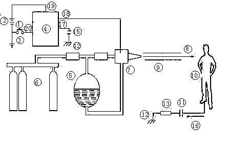
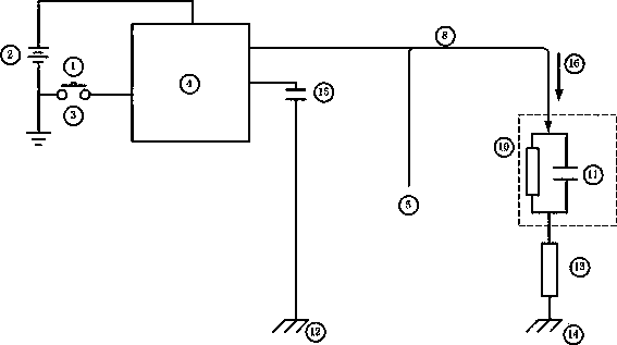
[0034] according to figure 1 , figure 2 Based on the principle and the above discussion, a hand-held single-beam jet electric shock device has been developed. The weight is 1.2kg, the output pulse high voltage is 50kV, the diameter of the jet is 1.5mm, and it hits the male volunteer at a distance of 7m. Volunteers jumped up involuntarily, felt muscle spasm, pain and fever at the hit site, which proved that the electric shock effect was obvious. The measured pulse electric shock current exceeds 100mA, which is basically consistent with the theoretical calculation results. After a 10-minute rest, the volunteers returned to normal. After a comprehensive examination by the hospital, no organic damage was caused.


PUM


Abstract

The invention discloses a single-beam jet flow electric shock device based on distribution parameter coupling. The single-beam jet flow electric shock device comprises a pulse high-voltage generator, a spraying nozzle and electrification jet flow liquid. The pulse high-voltage generator is arranged inside a body device, a plurality of lines are arranged on the pulse high-voltage generator, a closed switch is arranged on the first line, a battery is arranged on the second line, a trigger outside the body device is respectively connected with the closed switch and a mechanical device on a spraying nozzle pipe, the third line serves as a high voltage output end, the fourth line serves as a low voltage output end, the high voltage output end is connected with the spraying nozzle, the electrification jet flow liquid guided by protection gas is jetted out from the spraying nozzle to hit a living target object, a distributed capacitor between the living target object and the ground is coupled with a distributed capacitor between the ground and the low voltage output end, and a closed serial discharging circuit is formed. Strong but non-fatal-wound electric shock is generated to the living target object. The single-beam jet flow electric shock device is small in size, light in weight and capable of being held with one person, close-range continuous jetting within 7 m is achieved, a criminal suspect can be effectively subdued, or disorderly crowns can be effectively driven, and the single-beam jet flow electric shock device can serve as an updating substitute product of a Taser.

Description

technical field [0001] The invention relates to police high-voltage electric shock equipment, in particular to a single-beam jet electric shock device based on distributed parameter coupling. Background technique [0002] At present, domestic and foreign handheld police electric shock equipment are mainly electric batons and Taser guns. They are all double-electrode, that is, two electrodes need to act on the human body at the same time to produce electric shock effects. [0003] The electric baton is the most commonly used police equipment. It is often used to shock the human body or other living animals. During the electric shock, the two electrodes must touch each other's body at the same time to achieve a strong stimulating effect. It belongs to contact police equipment. Its disadvantage is that before the police officers give electric shocks, the suspect has the opportunity to have a direct physical confrontation with the police officers, and even hurt the...

Claims


Application Information

Patent Timeline
IPC IPC(8): F41B15/04
CPCF41H13/0037
Inventor 陆波
Owner JIANGSU FANHUA ELECTRONICS TECH
Learn More