
Electronic weighing machine capable of being connected and communication method thereof

An electronic, weighing instrument technology, used in non-electrical signal transmission systems, detailed information on weighing equipment, instruments, etc.

Inactive Publication Date: 2014-04-30
上海爱加科技有限公司
View PDF0 Cites 3 Cited by
  • Summary
  • Abstract
  • Description
  • Claims
  • Application Information

AI Technical Summary

Problems solved by technology

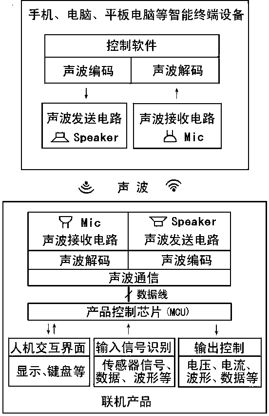
[0007] The purpose of this invention is to provide an intelligent electronic weighing instrument that can directly communicate with mobile phones, computers and other terminal equipment without data line connection, mainly to solve the current There is a problem that online electronic scales must communicate with mobile phones or computers through data cables

Method used


Image

  • Electronic weighing machine capable of being connected and communication method thereof
  • Electronic weighing machine capable of being connected and communication method thereof
  • Electronic weighing machine capable of being connected and communication method thereof

Examples


Embodiment 1

[0044] Embodiment 1: Using acoustic wave communication circuit and control chip scheme

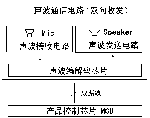
[0045] image 3 , Figure 4 , Figure 5 , Image 6 It is a description of the scheme that uses the combination of acoustic wave communication circuit and control chip to realize the online function.

[0046] image 3 It is the circuit structure diagram of the two-way transceiver embodiment composed of the product control chip and the acoustic wave communication circuit

[0047] The sound wave communication circuit consists of a sound wave codec chip, a sound wave receiving circuit, and a sound wave transmitting circuit to form a two-way sending and receiving sound wave communication circuit. The sound wave receiving circuit receives the external sound signal and transmits it to the sound wave codec chip. The A / D sampling circuit built in the sound wave codec chip converts the analog sound wave signal into a digital signal, and then passes through the built-in decoding program of the sou...

Embodiment 2

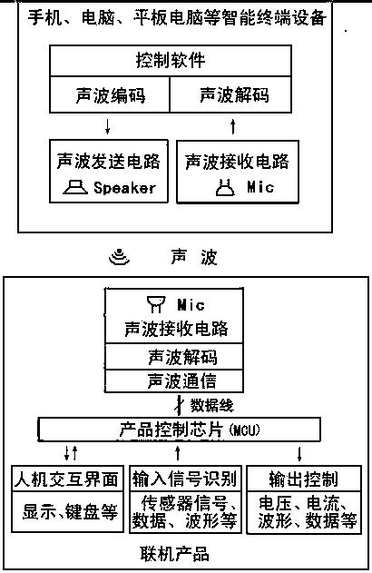
[0054] Example 2: Control chip built-in sound wave codec scheme

[0055] Figure 7 , Figure 8 , Figure 9 It is a description of the product control chip built-in A / D and D / A conversion and codec software.

[0056] Figure 7 It is a two-way communication circuit structure diagram in which the product control chip is directly connected with the sound wave receiving and transmitting circuit. The product control chip contains sound wave decoding circuit and decoding software or contains sound wave codec circuit and codec software. The analog sound wave signal received by the sound wave receiving circuit is converted into a digital signal by the A / D sampling circuit inside the product control chip, and then the sound wave signal of mainly 5KHz~25KHz is decoded by the built-in decoding program of the product control chip to obtain the relevant Instructions, the product control chip controls the human-computer interaction interface such as the display, the input signal identif...


PUM


Abstract

The invention relates to the field of counters and mainly discloses an electronic weighing machine which includes a weight balance, a kitchen scale, a human-body fat scale, a price-computing instrument, a weighing scale, a counting scale, a mass comparator and an analysis balance and the like and specifically relates to an intelligent electronic weighing machine. In a casing, a control chip is electrically connected with an output control circuit, a key input circuit, a display circuit, an input signal identification circuit and a wireless communication circuit. A problem that at present, electronic weighing machines are incapable of being connected with a computer or a handset is solved. To overcome defects of the prior art, the electronic weighing machine capable of being connected adopts a sound-wave communication method to enable the electronic weighing machine to be connected directly with a device such as a handset or a computer and the like so that setting of different functions of the electronic weighing machine can be performed on an intelligent terminal such as a handset or a computer.

Description

[0001] technical field [0002] The invention relates to the field of measuring instruments, mainly electronic weighing instruments, including weighing scales, kitchen scales, body fat scales, pricing scales, weighing scales, counting scales, mass comparators, analytical balances, etc., especially an intelligent electronic weighing instrument . Background technique [0003] Existing electronic scales, such as electronic scales, including weighing scales, kitchen scales, price scales, weighing scales, counting scales, quality comparators, analytical balances, etc., are composed of load cells, AD conversion circuits, single-chip microcomputer circuits, display circuit, keyboard circuit, communication interface circuit, regulated power supply circuit and other circuits. It can not only weigh various objects, but also has some humanized auxiliary functions. For example: a body scale with fat detection can also detect your own fat content. [0004] With the development of Int...

Claims


Application Information

Patent Timeline
Patent Type & Authority Applications(China)
IPC IPC(8): G01G23/00G08C23/02
Inventor 陈勇李勤
Owner 上海爱加科技有限公司
Learn More