
Force measurement wheel set calibration test stand

A force-measuring wheelset and test-bed technology, which is applied in the calibration/testing of force/torque/work measuring instruments, measuring devices, instruments, etc., can solve the problem that the test-bed cannot complete the automatic adjustment of the gauge and the influence of the test results is relatively large. , the operation process is cumbersome and other problems, to achieve the effect of simple rotation process, wide indexing range and high indexing accuracy

Active Publication Date: 2014-04-30
CRRC CHANGCHUN RAILWAY VEHICLES CO LTD
View PDF6 Cites 25 Cited by
  • Summary
  • Abstract
  • Description
  • Claims
  • Application Information

AI Technical Summary

Problems solved by technology

There are 4 sets of longitudinal limit devices, one on each side of each mast. The height is adjusted by the lifting motor driving the steel wire and other devices. The longitudinal limit is manually adjusted, which is inconvenient to operate. The head needs to be pushed against the bearing or the axle box horizontally and vertically Central location, the operation process is cumbersome and the reliability is low
[0005] 2. The test bench does not have a wheel set rotation mechanism, and the wheel set rotation is achieved manually. This type of rotation is not accurate, and the rotation process is cumbersome, which has a great impact on the test results.
[0006] 3. The test bench cannot complete the automatic adjustment of the gauge, and the longitudinal position needs to be manually adjusted for wheelsets of different rails, so the automation rate is extremely low

Method used


Image

  • Force measurement wheel set calibration test stand
  • Force measurement wheel set calibration test stand
  • Force measurement wheel set calibration test stand

Examples


Embodiment Construction

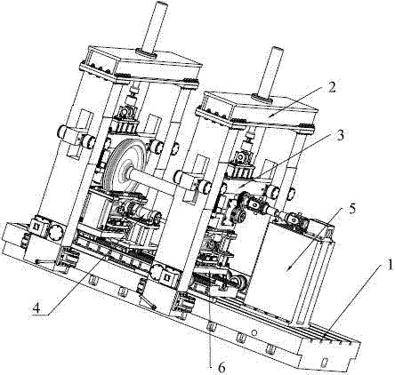
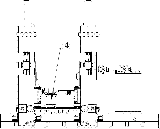
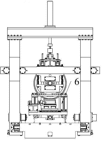
[0030] refer to Figure 1-4 , the force-measuring wheelset calibration test bench of the present invention comprises a T-type platform base 1, a gantry system 2, and a lateral loading system 4, and a vertical guide system 3 is installed on the gantry system, which is used to fix the wheelset and realize vertical loading. Loading in the direction of loading, the bottom plate system 6 is provided under the two gantry beams of the two gantry systems on the catwalk base 1, which is used to adjust the gauge, provide a platform for applying longitudinal force, and implement lateral limit on the wheel set, T One end of the type table base 1 is also provided with a wheel set rotation indexing system 5, which is used to realize the automatic rotation of the wheel set to load at any angle. The T-shaped platform base 1 is a cuboid structure, cast and processed, and the table is processed with T-shaped grooves for fixing the portal system 2 and the floor system 6 .

[0031] refer to Fi...


PUM


Abstract

A force measurement wheel set calibration test stand comprises a T-shaped stand base, portal systems and a transverse loading system. The force measurement wheel set calibration test stand is characterized in that perpendicular guide systems are installed on the portal systems and used for fixing a wheel set and achieving perpendicular loading; a bottom plate system is arranged at the position, below two portal top beams of the two portal systems, of the T-shaped stand base and used for adjusting track gauge, provides a platform for applying longitudinal force and transversely limiting the wheel set; a wheel set rotating indexing system is arranged at one end of the T-shaped stand base and used for achieving loading of any automatic rotating angle of the wheel set. According to the force measurement wheel set calibration test stand, perpendicular force and transverse force are independently loaded on the wheel set, and combined loading of loads in three directions can also be conducted on the wheel set; the force measurement wheel set calibration test stand has the wide track gauge calibration capacity, and meets the requirement for calibrating force measurement wheel sets of railway vehicles with the meter gauge, railway vehicles with the standard track gauge, railway vehicles with the wide gauge and other different railway vehicles; the force measurement wheel set calibration test stand has the capacity for adjusting lateral moving amount of wheel track contact points, and provides required perpendicular, transverse and longitudinal loads in a hydraulic loading mode.

Description

technical field [0001] The invention relates to a detection device in the field of rail vehicle dynamics, in particular to a novel force-measuring wheel-set calibration test bench for measuring the output characteristics of a force-measuring wheel set and wheel-rail force detection. Background technique [0002] With the development trend of high-speed and heavy-duty rail vehicles, the operation and safety performance of the vehicles are getting more and more attention. The force-measuring wheel set is the core sensor device in the research of rail vehicle dynamics test, and its performance directly affects the evaluation results of the tested objects. The dynamometer wheel set calibration test bench is the key equipment for calibrating the output characteristics of the dynamometer wheel set, checking various performance indicators of the dynamometer wheel set, and ensuring the measurement accuracy of the wheel-rail force. The lateral force, vertical force and longitudinal ...

Claims


Application Information

Patent Timeline
Patent Type & Authority Applications(China)
IPC IPC(8): G01L25/00
Inventor 王金田程亚军滕万秀马晓龙张永胜谭富星于寅刘春艳张彦吉玄东升
Owner CRRC CHANGCHUN RAILWAY VEHICLES CO LTD
Learn More