Rotary solar single-shaft tracking system
A single-axis tracking and solar energy technology, applied in the field of solar energy tracking systems, can solve the problems of complex structure, inability to rotate multiple shafts at the same time, low conversion efficiency of sunlight, etc., and achieve the effect of saving materials.
- Summary
- Abstract
- Description
- Claims
- Application Information
AI Technical Summary
Problems solved by technology
Method used
Image

Examples
Embodiment
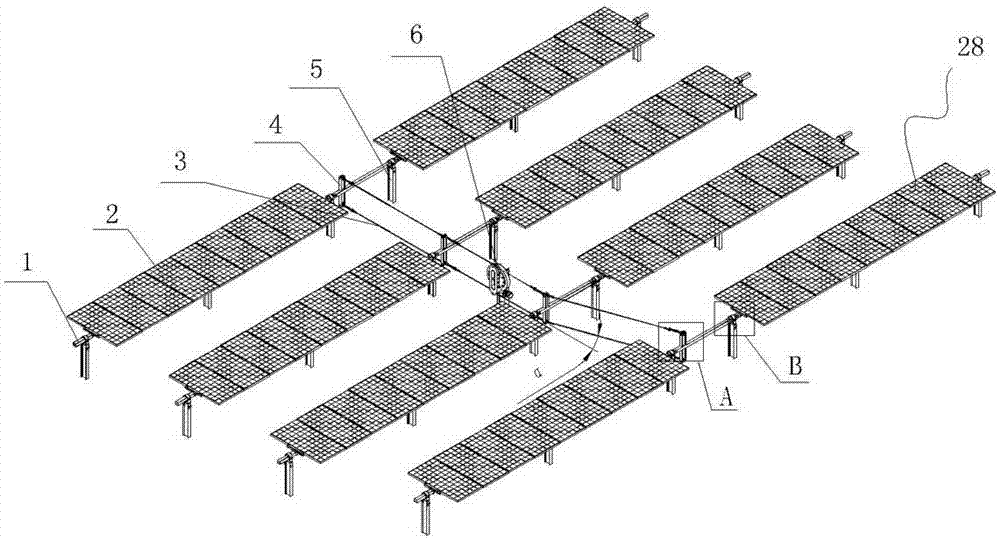
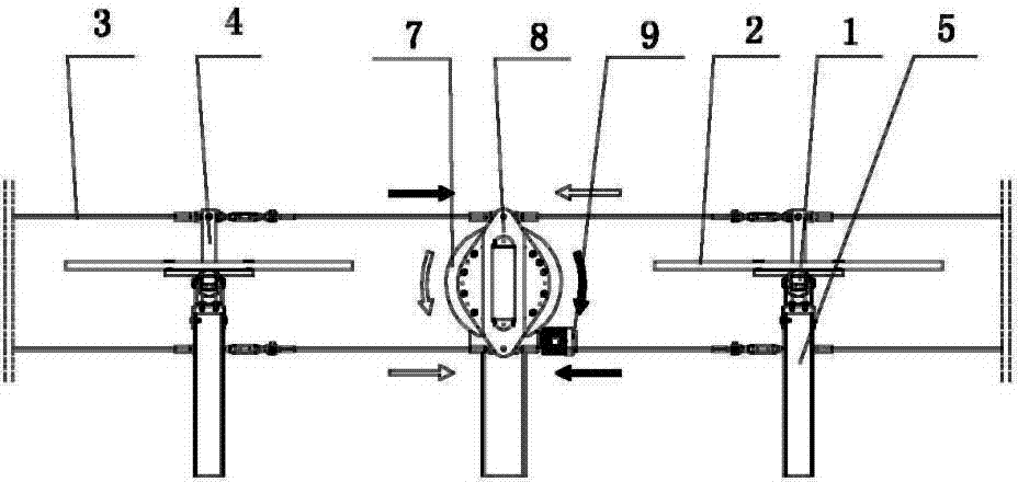
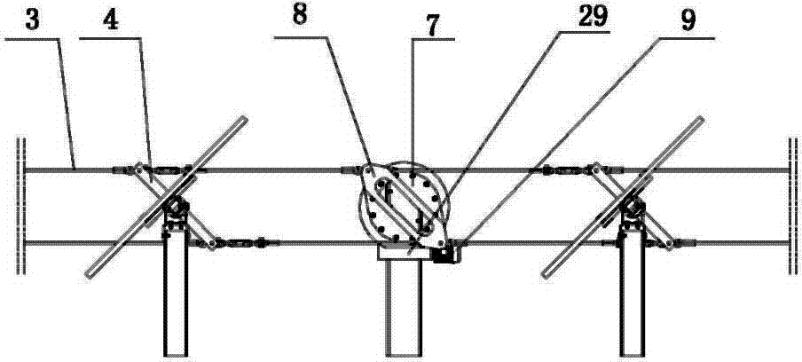
[0032] Such as figure 1 and 2 As shown in and 3, a rotary solar single-axis tracking system includes a plurality of solar photovoltaic module units 28, and the solar photovoltaic module unit 28 includes a column 5, on which a rotating shaft 1 is fixed, and a plurality of photovoltaic modules are fixed on the rotating shaft 1 component2. Each solar photovoltaic assembly unit 28 is arranged in a matrix form, and the rotating shafts 1 located in the same matrix are parallel to each other, and the two rotating shafts located in different matrices but on the same straight line are connected by a rotating shaft connection structure. The two ends of the rotating shaft 1 are fixed on the column through split square bearings.
[0033] A rotating arm 4 perpendicular to the rotating shaft is fixed on the rotating shaft 1. The rotating arm 4 includes an upper rotating arm 11 and a lower rotating arm 10, and the upper and lower rotating arms are all welded on the rotating shaft 1. The u...
PUM
| Property | Measurement | Unit |
|---|---|---|
| Angle | aaaaa | aaaaa |
Abstract
Description
Claims
Application Information
 - R&D
- Intellectual Property
- Life Sciences
- Materials
- Tech Scout
- Unparalleled Data Quality
- Higher Quality Content
- 60% Fewer Hallucinations
Browse by: Latest US Patents, China's latest patents, Technical Efficacy Thesaurus, Application Domain, Technology Topic, Popular Technical Reports.
© 2025 PatSnap. All rights reserved.Legal|Privacy policy|Modern Slavery Act Transparency Statement|Sitemap|About US| Contact US: help@patsnap.com