Cylindrical driven clamping type piezoelectric wriggle linear motor

A linear motor, clamping technology, applied in piezoelectric effect/electrostrictive or magnetostrictive motors, generators/motors, electrical components, etc., can solve the problems of low concentricity, large axial size, and control accuracy Low-level problems, to achieve the effect of high concentricity, small axial size, and small volume

Active Publication Date: 2014-04-30
HARBIN INST OF TECH
View PDF4 Cites 17 Cited by
  • Summary
  • Abstract
  • Description
  • Claims
  • Application Information

AI Technical Summary

Problems solved by technology

[0004] The present invention aims to solve the problem that the existing active-clamped peristaltic motors cannot be powered off and self-locked, and are not suitable for compact and slender motion mechanisms, and the passive-clamped peristaltic motors have large axial dimensions and require a separate guide mechanism. Low concentricity and low control precision, and then provide a cylindrical passive clamp piezoelectric creep linear motor

Method used


Image

  • Cylindrical driven clamping type piezoelectric wriggle linear motor
  • Cylindrical driven clamping type piezoelectric wriggle linear motor
  • Cylindrical driven clamping type piezoelectric wriggle linear motor

Examples


specific Embodiment approach 1

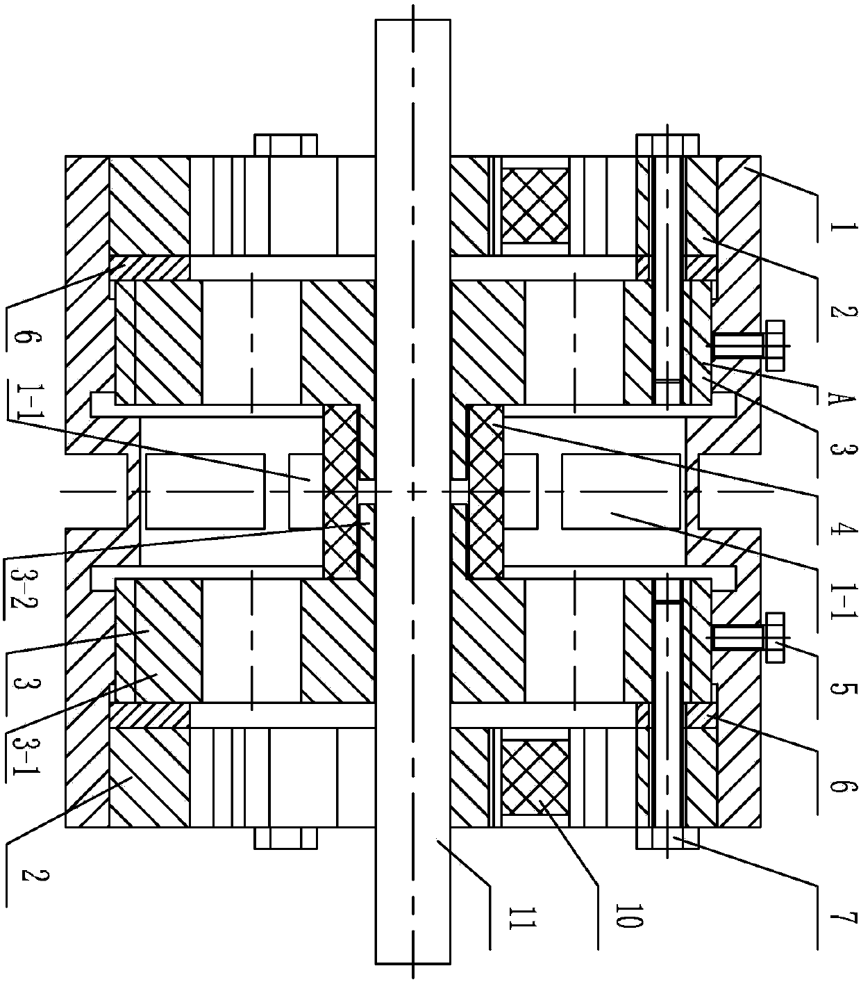
[0016] Specific implementation mode one: combine Figure 1-Figure 5 Illustrate, a kind of cylindrical passive clamp type piezoelectric peristaltic linear motor of this embodiment comprises guide rail 11, driving mechanism A, two annular washers 6 and two sets of clamping mechanisms B, each of said washers 6 is a circle Ring, the guide rail 11 is cylindrical;

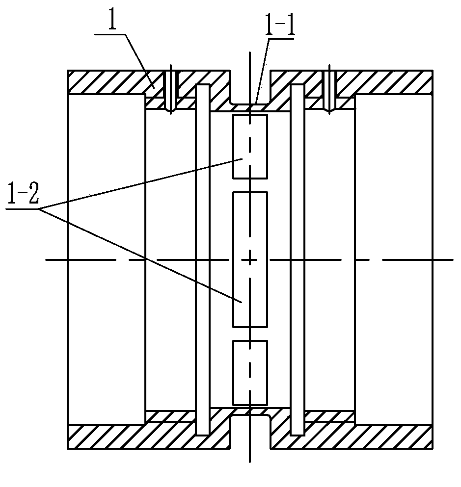
[0017] The drive mechanism A includes a drive sleeve 1, a first piezoelectric stack 4 and two clamping bodies 3; the drive sleeve 1 is cylindrical, and the first piezoelectric stack 4 is a hollow cylinder, each The clamping body 3 is a hollow cylinder;

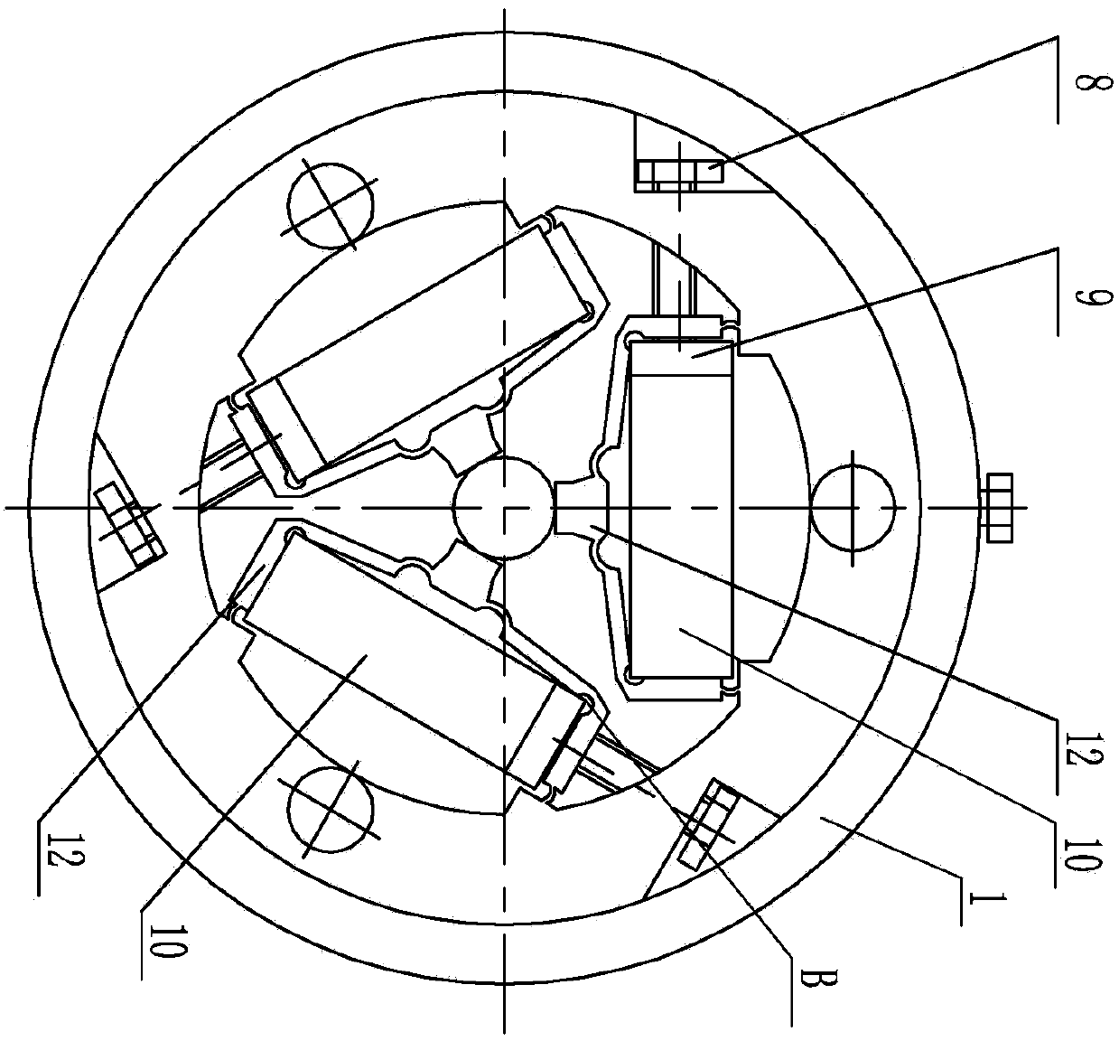
[0018] Each clamping mechanism B includes a clamping body 2, three second piezoelectric stacks 10 and three flexible bodies 12; each clamping body 2 is a hollow cylinder, and each second piezoelectric stack 10 is a cuboid , the section of each flexible body 12 is {-shaped;

[0019] A first piezoelectric stack 4 is installed in the middle of the driving sleeve 1, and a...

specific Embodiment approach 2

[0020] Specific implementation mode two: combination figure 2 To illustrate, the clamping body 2 of this embodiment is in clearance fit with the drive sleeve 1 . Such arrangement ensures the relative movement of the clamping body and the driving sleeve. Others are the same as in the first embodiment.

specific Embodiment approach 3

[0021] Specific implementation mode three: combination figure 1 To illustrate, the washer 6 in this embodiment is in clearance fit with the drive sleeve 1 . In this way, the axial compression of the clamping body, the clamping body and the washer will not affect the circumferential deformation of the flexible mechanism on the clamping elastic body, which is beneficial to realize the triangular displacement amplification of the flexible body on the clamping body. Others are the same as in the first or second embodiment.


PUM


Abstract

The invention relates to a piezoelectric drive device, in particular to a cylindrical driven clamping type piezoelectric wriggle linear motor to solve the problems that an existing drive clamping type wriggle motor cannot be powered off or self-locked and is not suitable for a compact, thin and long motion mechanism, and a driven clamping type wriggle motor is large in axial size and low in concentricity and control precision and needs an independent guide mechanism. The cylindrical driven clamping type piezoelectric wriggle linear motor comprises a guide rail, a drive mechanism, two annular gaskets and two sets of clamping mechanisms. The drive mechanism comprises a drive sleeve, a first piezoelectric stack and two clipping bodies. Each set of clamping mechanism comprises a clamping body, three second piezoelectric stacks and three flexible bodies. The middle of the drive sleeve is provided with the first piezoelectric stack, the clipping bodies, the gaskets and the clamping bodies are installed inside the drive sleeve from interior to exterior in a left-and-right symmetrical mode, the clipping bodies are in threaded connection with the drive sleeve, and the three flexible bodies are respectively and evenly distributed on the inner surfaces of the clamping bodies in the circumferential direction of the clamping bodies. The piezoelectric drive device is applied to the precise positioning and driving field.

Description

technical field [0001] The invention relates to a piezoelectric drive device, in particular to a passive clamp type piezoelectric peristaltic linear motor, which belongs to the field of piezoelectric precision drive. Background technique [0002] With the continuous development of science and technology, there is an urgent need for ultra-precise linear positioning drives in the optical field, semiconductor field, and machining industry. Traditional positioning devices have certain deficiencies, such as clearance and stick-slip. Drive equipment in many cutting-edge technology fields is developing towards small size, light weight, high precision and high performance, and traditional electromagnetic motors are difficult to meet the current requirements. The characteristics of the bionic inchworm drive based on the principle of creep determine that it has obvious advantages in the application of precision drive positioning with submicron or nanometer precision and a stroke of m...

Claims


Application Information

Patent Timeline
Patent Type & Authority Applications(China)
IPC IPC(8): H02N2/04
Inventor 曲建俊黄辉郭文峰
Owner HARBIN INST OF TECH
Why Eureka
Try Eureka