Zipper slider
A technology for zippers and sliders, applied in the field of sliders for zippers, which can solve the problems of damage to the elastic sheet, increased cost of the slider 90, and complex structure, and achieve the effect of simplifying the structure
- Summary
- Abstract
- Description
- Claims
- Application Information
AI Technical Summary
Problems solved by technology
Method used
Image
Examples
Embodiment 1
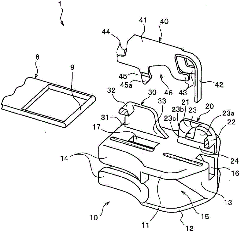
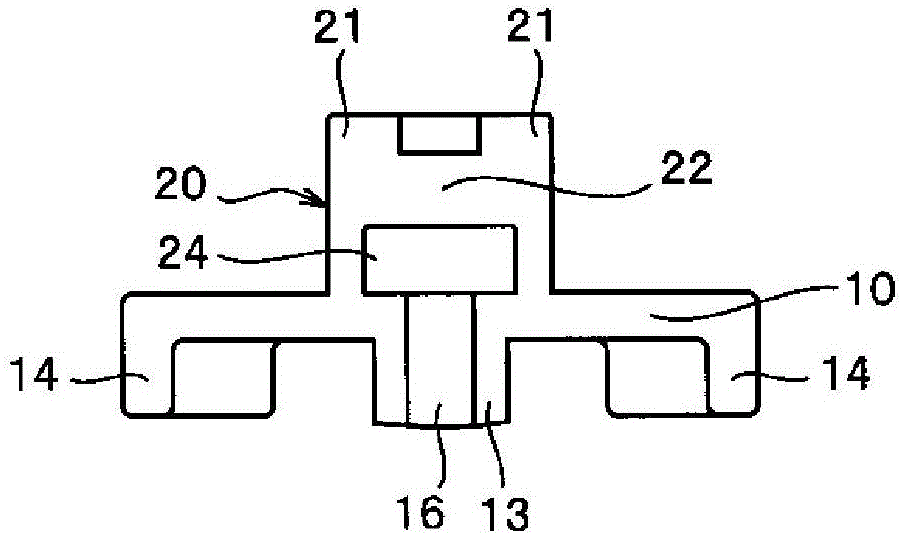
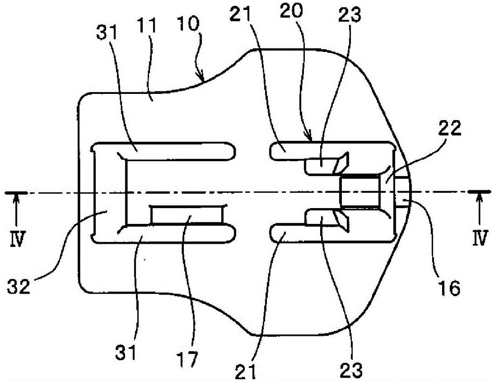
[0133] figure 1 It is an exploded perspective view showing a disassembled state of the slider related to the first embodiment, figure 2 It is an enlarged front view showing the main part of the slider body of the slider. also, image 3 is the top view of the main body of the slider, Figure 4 is along image 3 Sectional view along line IV-IV shown.
[0134] In addition, in figure 1 In order to facilitate the understanding of the features of the slider according to the first embodiment, illustration of the front side wall and the rear side wall of one (right side) of the front mounting part and the rear mounting part is omitted. In addition, in Figure 4 In , in order to clearly show the position of the stop claw disposed on the right side wall of the cover member, the stop claw that is not actually shown in this cross-sectional view is indicated by a dotted line.
[0135] In addition, in the following description, the front-back direction of a slider refers to the dire...
Embodiment 2
[0194] Figure 12 It is a sectional view showing the slider related to the second embodiment, Figure 13 It is a side view which shows the cover of this slider.
[0195] In addition, in the present embodiment 2 and the later-described embodiment 3, the structure different from that of the slider 1 related to the above-mentioned embodiment 1 will be mainly described, and the structures related to the above-mentioned embodiment 1 will be denoted by using the same reference numerals. The components or members of the slider 1 have substantially the same structure, and their descriptions are omitted.
[0196] The slider 2 according to the second embodiment includes: a slider main body 10a, a handle 8 having an installation shaft 9 , and a cover member 40a, and a downward-facing hook is disposed on the front end of the locking piece 43 of the cover member 40a. The engaging portion 47 is in a curved form.
[0197] In addition, on the upper blade 11a of the slider main body 10a, an...
Embodiment 3
[0201] Figure 14 It is a schematic diagram showing the slider main body and the cover member constituting the slider according to the third embodiment, Figure 15 is an enlarged view of main parts showing main parts of the slider. In addition, in Figure 14 In order to easily determine the characteristics of the slider according to the third embodiment, the slider main body is shown in cross-sectional view, and the cover member is shown in side view.
[0202] The slider 3 according to the third embodiment includes a slider main body 50 , a handle 8 having an attachment shaft portion 9 , and a cover member 60 .
[0203] The cover member 60 includes: a cover main body 61 with an inverted U-shaped cross section; a sheet-shaped elastic piece 62 extending from the front end of the upper surface of the cover main body 61; The extended locking piece 63; the protruding piece 64 protruding rearward from the lower end of the left and right side walls of the cover main body 61; The ...
PUM
 Abstract
Description
Claims
Application Information
 - R&D
- Intellectual Property
- Life Sciences
- Materials
- Tech Scout
- Unparalleled Data Quality
- Higher Quality Content
- 60% Fewer Hallucinations
Browse by: Latest US Patents, China's latest patents, Technical Efficacy Thesaurus, Application Domain, Technology Topic, Popular Technical Reports.
© 2025 PatSnap. All rights reserved.Legal|Privacy policy|Modern Slavery Act Transparency Statement|Sitemap|About US| Contact US: help@patsnap.com


