Linear feeding and discharging mechanism of full-automatic bar chamfering machine

A feeding mechanism and fully automatic technology, applied in the direction of grinding feed movement, machine tools suitable for grinding workpiece edges, grinding workpiece supports, etc., can solve equipment efficiency loss, excessively long conveying line, workpiece collapse, etc. problems, to avoid waste of working hours, reduce personnel costs, and avoid dust pollution

Active Publication Date: 2014-05-07
XIAMEN TUNGSTEN
View PDF10 Cites 16 Cited by
  • Summary
  • Abstract
  • Description
  • Claims
  • Application Information

AI Technical Summary

Problems solved by technology

This action mode caused the waiting of the manipulator feeding process, resulting in the loss of equipment efficiency
At the same time, the ejecting mechanism and the receiving mechanism caused the conveying line to be too long, and the action of ejecting materials is also likely to cause the collapse of the workpiece, resulting in defective products.

Method used


Image

  • Linear feeding and discharging mechanism of full-automatic bar chamfering machine
  • Linear feeding and discharging mechanism of full-automatic bar chamfering machine
  • Linear feeding and discharging mechanism of full-automatic bar chamfering machine

Examples


Embodiment

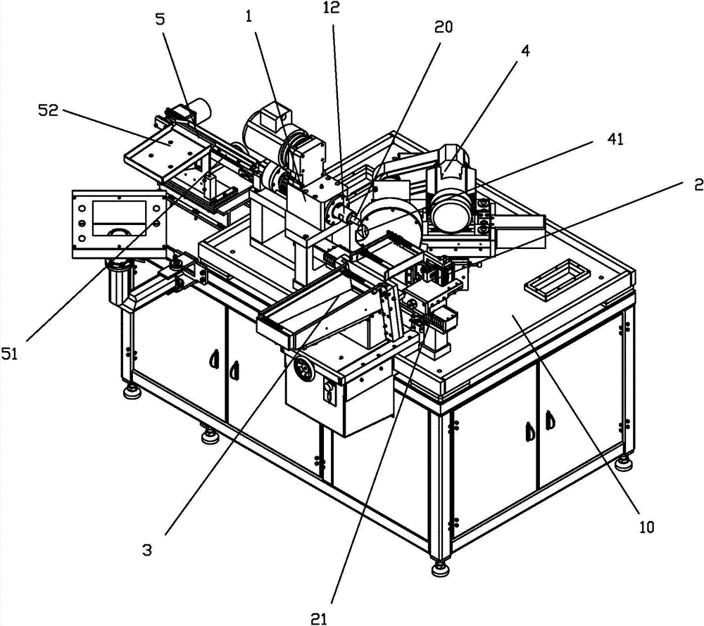
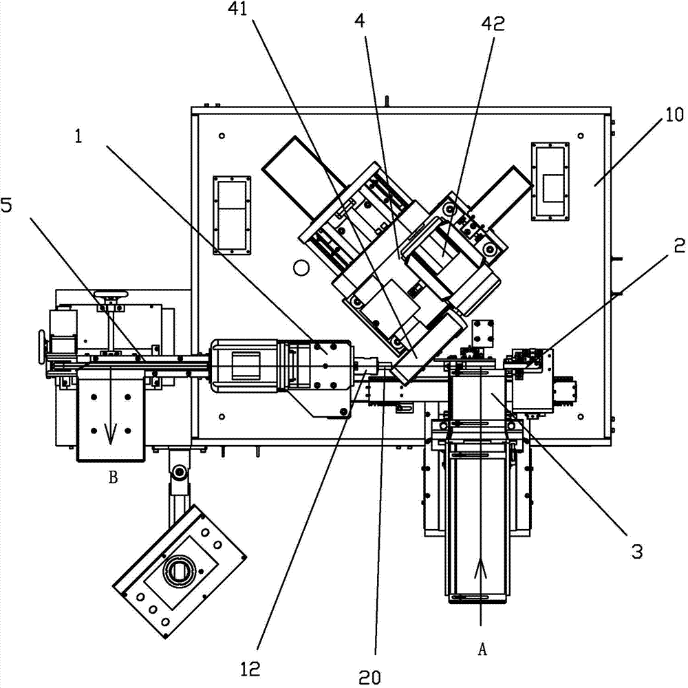
[0027] see Figure 1 to Figure 5 As shown, the linear feed-in and discharge mechanism of a kind of bar stock full-automatic chamfering machine of the present invention comprises:

[0028] A working head mechanism 1, the working head mechanism 1 includes a collet 11 that can be used to clamp the bar stock and a main shaft 12 that is used to drive the collet to rotate; the main shaft 12 is provided with a hollow inner chamber, so that the bar stock at the front end 20 send out to the rear end along the hollow inner cavity;

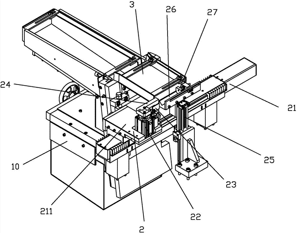
[0029] A feeding mechanism 2, the feeding mechanism 2 is arranged at a position adapted to the front end of the working head mechanism 1; the feeding mechanism 2 includes a linear feeding precision linear module 21 capable of rectilinear reciprocating motion, the linear The feeding precision linear module 21 is arranged at a position capable of reciprocating linearly along the axial direction of the main shaft of the working head mechanism, so as to be able...


PUM


Abstract

The invention discloses a linear feeding and discharging mechanism of a full-automatic bar chamfering machine. The linear feeding and discharging mechanism of the full-automatic bar chamfering machine comprises a work head mechanism, a feeding mechanism and a receiving mechanism. The work head mechanism comprises a clamping head used for clamping bars and a spindle used for driving the clamping head to rotate. A hollow inner cavity is formed in the spindle, and the bars at the front end of the spindle can be conveyed out toward the rear end of the spindle along the hollow inner cavity. The feeding mechanism comprises a linear feeding precision linear module which can make linear reciprocating movement, and the linear feeding precision linear module is arranged at the position where linear reciprocating movement can be made in the axis direction of the spindle of the work head mechanism to enable the bars of the work head mechanism to be pushed in the hollow inner cavity of the spindle along a straight line. The receiving mechanism is arranged to enable the bars discharged by the hollow inner cavity of the work head mechanism to be conveyed to a receiving position in a linear mode. According to the linear feeding and discharging mechanism, the feeding mode is changed into a front positioning mode from a rear positioning mode, the feeding mode of front feeding and front discharging is changed into a work head inside linear discharging mode, so that the entire structure of the mechanism is compact, and the production efficiency and the product percent of pass are improved while the requirement for precision can be met.

Description

technical field [0001] The invention relates to the technical field of mechanical processing, in particular to a linear feeding and discharging mechanism of a bar full-automatic chamfering machine. Background technique [0002] Existing bar chamfering machine mainly contains two kinds, and a kind of is manual tool grinder, and another kind is automatic chamfering machine. [0003] The main structure of the manual tool grinder is a grinding wheel mechanism, a sliding platform and a chuck clamping mechanism. When working, the chuck clamping mechanism clamps the bar to rotate, driven by the sliding platform, and reciprocates through the rotating grinding wheel on the grinding wheel mechanism at a certain angle to complete Grinding. The manual tool grinder is positioned after the tooling, and the bar is clamped by the manual three-grip chuck clamping method. When operating, the operator must hold the bar with one hand and lock it with the other. This method determines the poor ...

Claims


Application Information

Patent Timeline
Patent Type & Authority Applications(China)
IPC IPC(8): B24B9/00
CPCB24B9/00B24B41/005B24B41/061
Inventor 凌秉达乐赞扬王立杰臧文海张大伟吴冲浒
Owner XIAMEN TUNGSTEN
Why Eureka
Try Eureka