A mold for processing U-shaped water tank

A mold and water tank technology, applied in the field of molds for processing U-shaped water tanks, can solve the problems of large floor space, many internal bubbles, low product strength, etc., and achieve the effect of saving floor space, less internal bubbles, and high product strength

Active Publication Date: 2015-12-02
HEILONGJIANG PROVINCIAL HYDRAULIC RES INST
View PDF4 Cites 0 Cited by
  • Summary
  • Abstract
  • Description
  • Claims
  • Application Information

AI Technical Summary

Problems solved by technology

[0003] The purpose of the present invention is to solve the problems of rough surface, many internal air bubbles, low product strength and low yield of U-shaped water tanks produced by existing molds for processing U-shaped water tanks; and the length of the finished product is only 500 mm, and the cross-section occupies a large area. As a result, the U-shaped water tank has many joints, poor durability and large floor space when it is used in the water channel, and a mold for processing U (rectangular) water tank is provided.

Method used


Image

  • A mold for processing U-shaped water tank
  • A mold for processing U-shaped water tank
  • A mold for processing U-shaped water tank

Examples


specific Embodiment approach 1

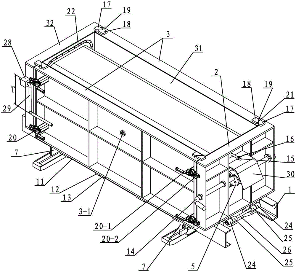
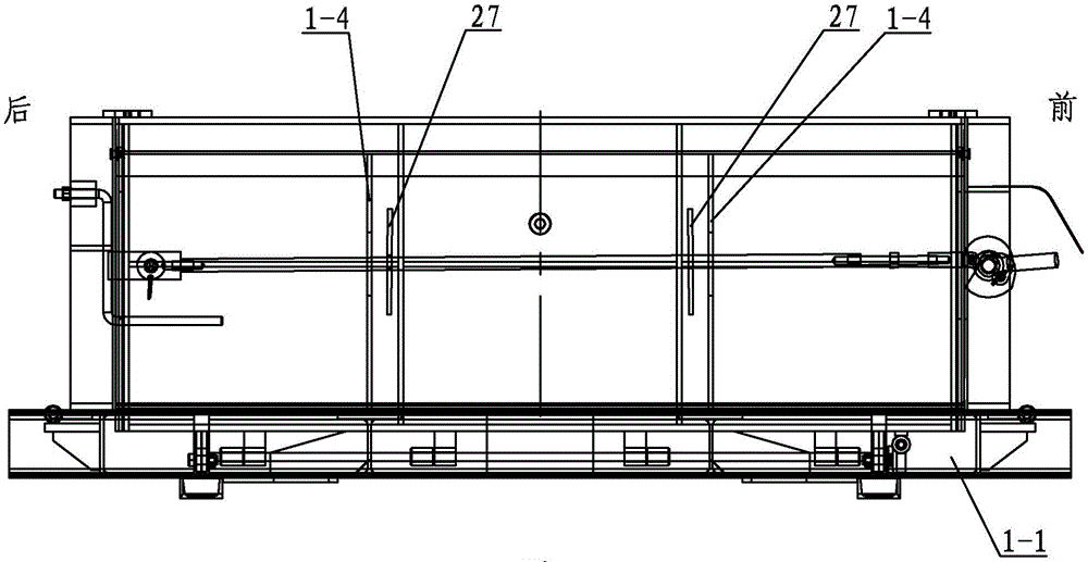
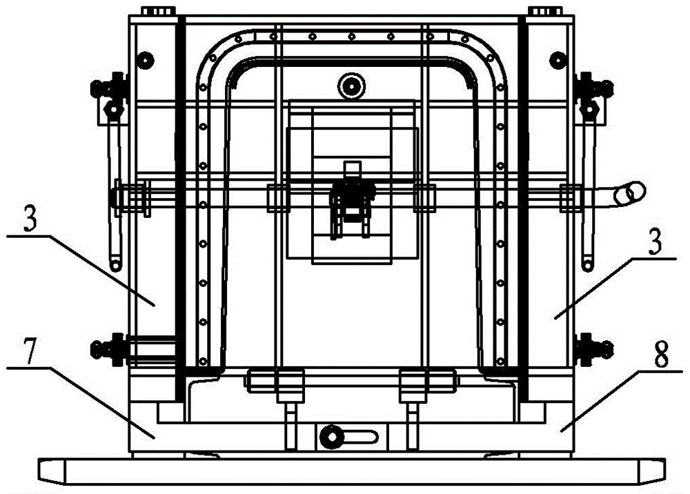
[0023] Specific implementation mode one: combine Figure 1 to Figure 12Describe this embodiment. This embodiment includes a chassis assembly 1, a front mold assembly 2, a rear mold assembly 32, an end mold linkage assembly 5, a switch shaft 14, two side mold assemblies 3, and two left mold assemblies. Linkage plate 7, two right side mold linkage plates 8, two connecting elements 9, two side hinge bars 11, two inverted U-shaped gaskets 22, two end hinge bars 26, four end mold positioning obliques Plate 17, four side mold positioning inclined plates 18, four positioning shafts 19, four bottom frame end hinged sleeves 24, four end mold assembly hinged sleeves 25, eight quick clamps 20, several bottom frame side hinged sleeves 12 and several side mold assembly hinge sleeves 13, the chassis assembly 1 includes an inverted U-shaped plate 1-2, two longitudinal beams 1-1, two inverted U-shaped end plates 1-3, and two inverted U-shaped ribs Plate 1-4 and two beams 1-5, two longitudina...

specific Embodiment approach 2

[0024] Specific implementation mode two: combination figure 1 Describe this embodiment, the hasp 20-1 on the quick clamp 20 of this embodiment is installed on the side mold assembly 3, and the snap hook 20-2 on the quick clamp 20 is installed on the corresponding front mold assembly 2 and the rear end On the mold assembly 32. Quick clamp 20 makes front end mold assembly 2 and rear end mold assembly 32 and two side mold assemblies 3 realize fast locking, makes front end mold assembly 2 and rear end mold assembly 32 and two side mold assemblies 3 form a solid whole. Other components and connections are the same as those in the first embodiment.

specific Embodiment approach 3

[0025] Specific implementation mode three: combination figure 1 This embodiment is described. The difference between this embodiment and the specific embodiment 1 or 2 is that it also adds an opening and closing clamping rod 15 and a clamping nut 16. The opening and closing clamping rod 15 is arranged on the front-end mold assembly 2, and One end of the opening and closing clamping rod 15 is fixedly connected with the U-shaped end plate 1-3, and the other end of the opening and closing clamping rod 15 passes through the front-end mold assembly 2 and is threadedly connected with the clamping nut 16. The opening and closing position pull rod 15 is used to limit the opening angle of the front mold assembly 2 . Other compositions and connections are the same as those in Embodiment 1 or 2.


PUM


Abstract

A U-shaped sink machining mould relates to U-shaped sink machining moulds and solves the problem that a U-shaped sink machined with an existing U-shaped sink machining mould has the length of only 500 meters as well as the problem of dimensions of cross section structures. A front end mould assembly, a rear end mould assembly and two side mould assemblies form a four-side frame, the four-side frame is arranged on a base frame assembly, both ends of the lower portion of the left side mould assembly is respectively provided with a left side mould linkage plate, both ends of the lower portion of the right side mould assembly is respectively provided with a right side mould linkage plate, the left side mould linkage plate and the right side mould linkage plate which transversely correspond to each other are hinged through a connecting member, a side hinge rod is arranged between two left side mould linkage plate, a switch shaft is mounted on the front end mould assembly, two sector connecting plates on an end mould linkage assembly are connected with the switch shaft and fixedly connected with the rear end mould assembly, and four corners of the outer side wall of each of the side mould assemblies is respectively mounted with a quick clamp. The U-shaped sink machining mould is used for machining a U-shaped sink for water channel construction.

Description

technical field [0001] The invention relates to a mold for processing a water tank, in particular to a mold for processing a U-shaped water tank. Background technique [0002] The existing mold for processing U-shaped water tanks consists of an inner mold and an outer mold. Dry hard concrete is poured between the inner mold and the outer mold and then squeezed by a vibrating bridge. The U-shaped water tank made by this method has the following defects: The surface of the product is rough, there are many internal bubbles, the product strength is low, and the finished product rate of the processed U-shaped water tank is low; and the length of the finished product is only 500mm, and the cross-section covers a large area. The U-shaped water tank has many joints after being used in the water channel, and the durability is poor. The effect of water transfer and water saving is poor and the floor area is large. Contents of the invention [0003] The purpose of the present invent...

Claims


Application Information

Patent Timeline
Patent Type & Authority Patents(China)
IPC IPC(8): B28B7/26
CPCB28B7/0002B28B7/0029
Inventor 孙景路曲祥民刘道维耿贺松张滨张守杰司振江刘丽佳刘建明钟华吴志琴李兆宇岳为群
Owner HEILONGJIANG PROVINCIAL HYDRAULIC RES INST
Why Eureka
Try Eureka