Straw gasification furnace

A gasifier and straw technology, applied in the field of gasifier, can solve the problems of excessively burning straw and frequent feeding, and achieve the effects of good effect, resource saving and environmental protection

Inactive Publication Date: 2014-05-07
张志民
View PDF0 Cites 0 Cited by
  • Summary
  • Abstract
  • Description
  • Claims
  • Application Information

AI Technical Summary

Problems solved by technology

[0004] The purpose of the present invention is to provide a straw gasifier to solve the problem of too fast burning of straw and frequent feeding

Method used


Image

  • Straw gasification furnace
  • Straw gasification furnace

Examples


Embodiment Construction

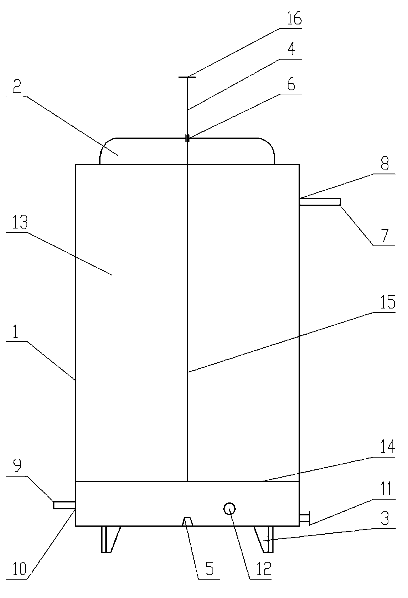
[0013] The structure of the straw gasifier is as follows: figure 1 As shown, the furnace body 1 is fixedly installed on the support 3 , and the furnace cover 2 is installed on the top of the furnace body 1 to form a gasification chamber 13 inside the furnace body 1 .

[0014] The bottom of the furnace body 1 is respectively provided with an ash outlet 11 and an ignition outlet 12, and the ash outlet 11 and the ignition outlet 12 can also be combined into one. An air inlet pipe 9 is connected to the bottom of the body of furnace 1, and a dust blocking filter screen 10 is arranged on the air inlet pipe 9. The upper part of the furnace body 1 is provided with a combustible gas passage 7, and a filter 8 is installed on the combustible gas passage 7.

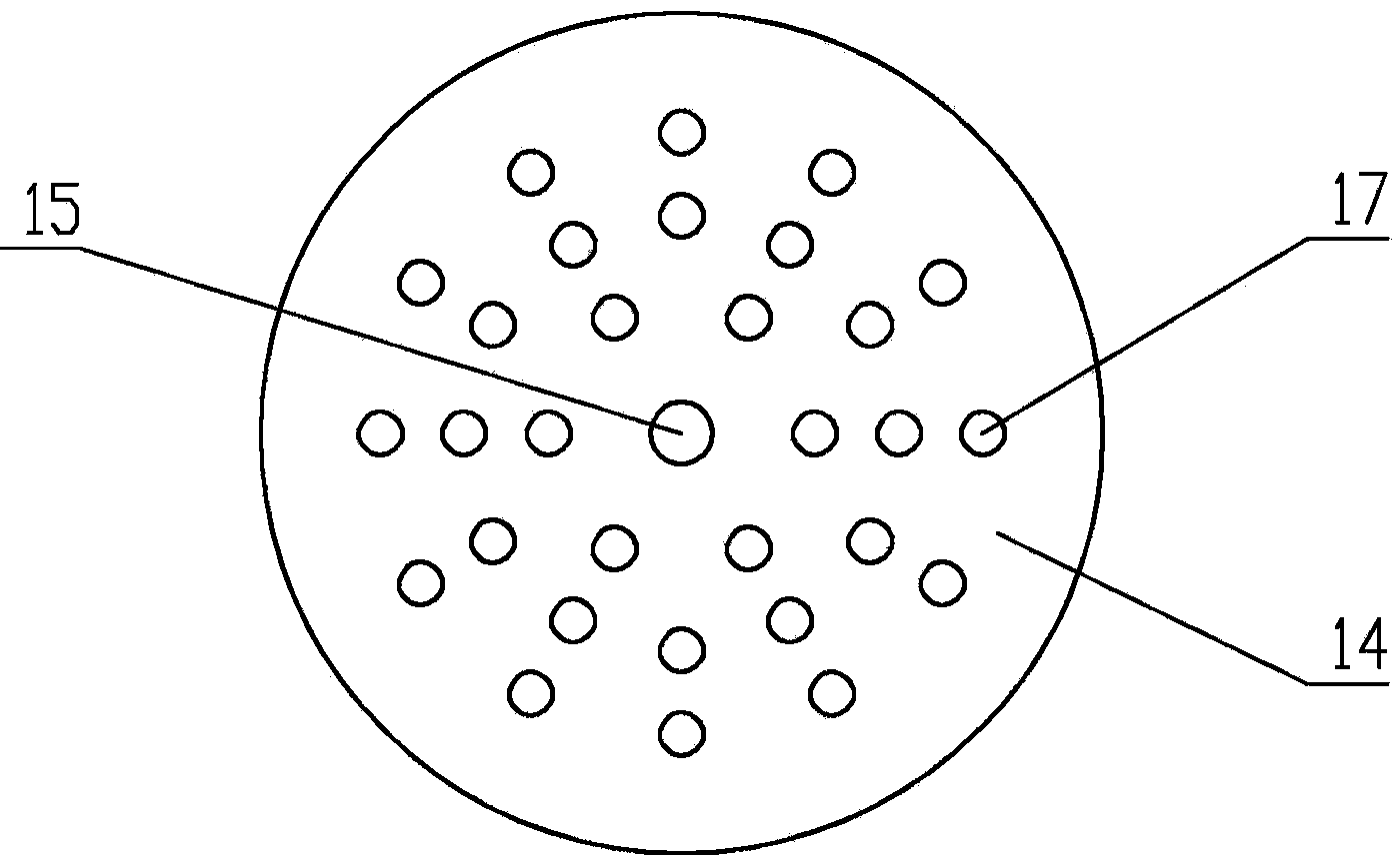
[0015] Compactor 4 is installed in the body of furnace 1, and its structure is as figure 2 As shown, it is composed of a compactor chassis 14 and a pull rod 15, the diameter of the compactor chassis 14 is slightly smaller than the...


PUM


Abstract

A straw gasification furnace comprises a furnace body, supports and a furnace cover, and further comprises a compactor, wherein the compactor comprises a chassis and a pull rod; the chassis is horizontally arranged in the furnace body; the pull rod penetrates the furnace body from the furnace cover, and is fixedly connected with the chassis; the chassis is pulled to move up and down in the furnace body to compact straw, so that the straw can be completely burnt to generate combustible gases sufficiently, the gas-producing duration time is long, and the effect is good.

Description

technical field [0001] The invention relates to a gasification furnace, in particular to a straw gasification furnace. Background technique [0002] The output of straw in rural areas is large, but because of its insignificant use value, it is often discarded or burned randomly. This treatment method not only causes waste of straw materials, but also seriously pollutes the environment. [0003] The straw gasification furnace is a device that uses compressed straw as raw material to generate combustible gas through dry distillation, pyrolysis or thermochemical oxidation under airtight anoxic conditions. The currently used straw gasifiers generally have the disadvantages of too fast burning of straw and frequent feeding. Contents of the invention [0004] The purpose of the present invention is to provide a straw gasifier to solve the problem of too fast burning of straw and frequent feeding. [0005] In order to solve the above technical problems, the present invention ad...

Claims


Application Information

Patent Timeline
Patent Type & Authority Applications(China)
IPC IPC(8): C10J3/20C10J3/72
Inventor 张志民
Owner 张志民
Why Eureka
Try Eureka